“A” Group: Standard Functions
Configuring Drive
Parameters
3–14
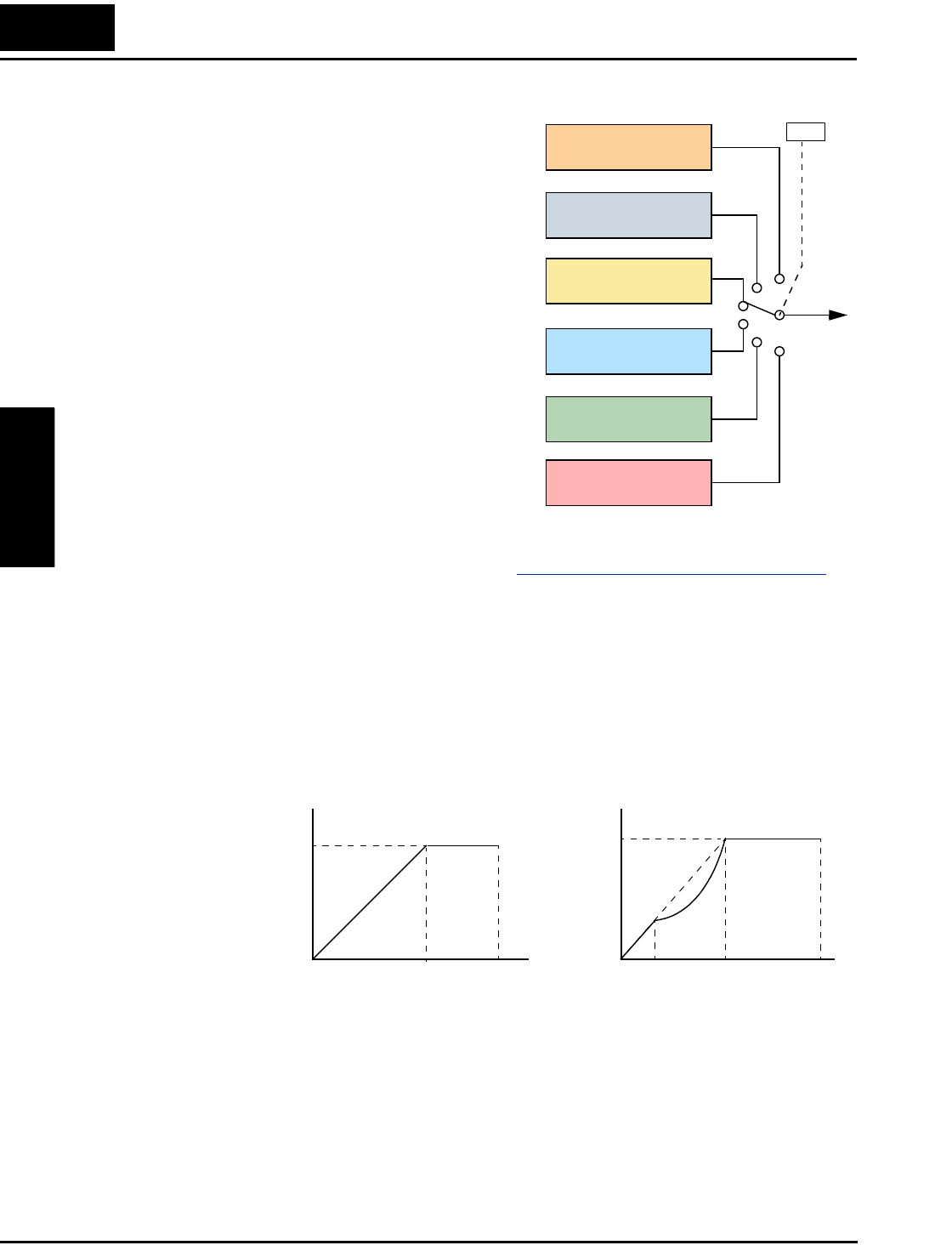
Torque Control
Algorithms
The inverter generates the motor output
according to the V/f algorithm or the
sensorless vector control algorithm. Param-
eter A044 selects the inverter torque control
algorithm for generating the frequency
output, as shown in the diagram to the right
(A244 and A344 for 2nd and 3rd motors,
respectively). The factory default is 00
(constant torque V/f control).
Review the following descriptions to help
you choose the best torque control
algorithm for your application.
• The built-in V/f curves are oriented
toward developing constant torque or
variable torque characteristics (see
graphs below).
• The free-setting curve provides an even
more flexible characteristic, but it
requires more parameter settings.
• Sensorless vector control calculates an
ideal torque vector based on current
motor position, winding currents, and so
on. It is a more robust control method than the V/f control methods. However, it is more
dependent on actual motor parameters and will require you to set these values carefully or to
perform the auto-tuning procedure (see “
Auto-tuning of Motor Constants” on page 4–67) to
obtain optimum performance.
• Sensorless vector control, 0Hz domain increases the low-speed torque performance (0–
2.5Hz) via an advanced Hitachi torque control algorithm. However, you will need to size the
inverter for one frame size larger than the motor for proper operation.
• Vector control with sensor requires expansion card SJ–FB encoder feedback board and a
motor shaft encoder. Choose this method when precise position/velocity control is required.
Constant and Variable Torque – The graph below (left) shows the constant torque character-
istic from 0Hz to the base frequency A003. The voltage remains constant for output frequencies
higher than the base frequency.
The graph above (right) shows the general characteristic for variable torque. The curve may be
best described in three sections, as follows:
a. The range from 0Hz to 10% of the base frequency is the constant torque characteristic.
For example, a base frequency of 60Hz ends the constant torque characteristic segment
at 6Hz.
b. The range from 10% of the base frequency to the base frequency is the variable
(reduced) torque characteristic. The voltage is output in the curve of frequency to the 1.7
power.
Output
V/f control,
constant torque
V/f control,
variable torque
V/f control, free-
setting curve
Inverter Torque Control Algorithms
Sensorless vector
(SLV) control
Sensorless vector,
0Hz domain
Vector control with
sensor
00
05
04
03
02
01
A044
Constant torque Variable torque
Maximum
frequency
Base
frequency
100%
100%
Maximum
frequency
Base
frequency
Output
voltage
Output
voltage
10% of
base
frequency
a.
b. c.
00


