


SJ300 Inverter
Operations
and Monitoring
4–11
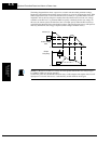
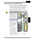
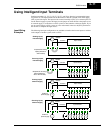
Using Intelligent Input Terminals
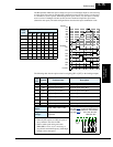
Intelligent terminals [1], [2], [3], [4], [5], [6], [7], and [8] are identical, programmable inputs
for general use. The input circuits can use the inverter’s internal (isolated) +24V field supply
(P24) to power the inputs. The input circuits connect internally to [PLC] as a common point. To
use the internal supply to power the inputs, use the jumper as shown. Remove the jumper to use
an external supply, or to interface to a PLC system (or other) that has solid state outputs. If you
use an external supply or PLC system, its power return must connect to the [PLC] terminal on
the inverter to complete the input circuit.
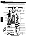
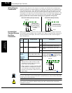
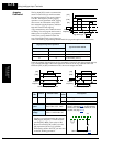
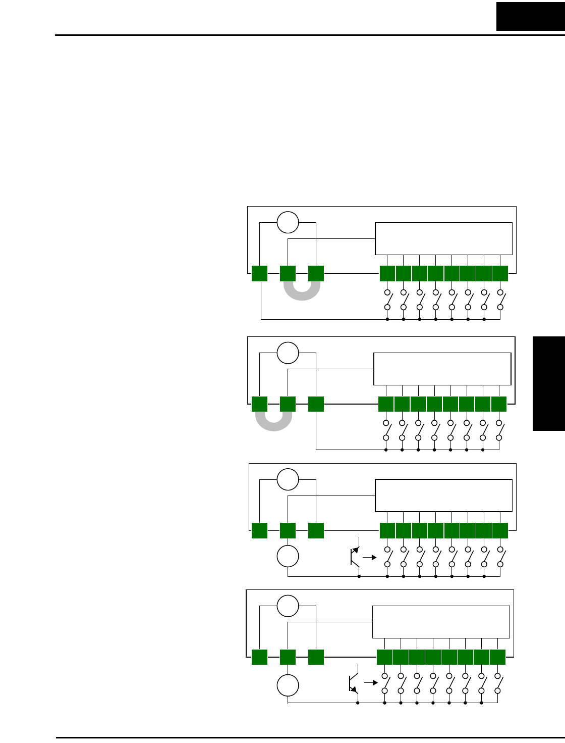
Input Wiring
Examples
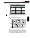
The following four input configurations are available to interface the inverter inputs to switches
or the outputs of another system, such as a PLC.
5 3 17 6 4 28
Input circuits
+
–
24VDC
common
Sinking inputs,
internal supply
SJ300 inverter
5 3 1
PLC
CM1
7 6 4 28
Input circuits
+
–
24VDC
common
SJ300 inverter
5 3 17 6 4 28
Input circuits
+
–
24VDC
common
External
power supply
SJ300 inverter
5 3 17 6 4 28
Input circuits
+
–
24VDC
common
SJ300 inverter
Sourcing inputs,
internal supply
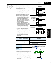
Sinking inputs,
external supply
Sourcing inputs,
external supply
External
power supply
P24
PLC
CM1
P24
PLC
CM1
P24
PLC
CM1
P24
+
–
+
–
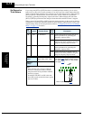
Jumpered for sinking
inputs (default for
–xFE models)
Jumpered for sourcing
inputs (default for
–xFU/–xFR models)