


Dynamic Braking
Motor Control
Accessories
5–6
Dynamic Braking
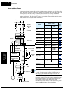
Introduction The purpose of dynamic braking is to improve the ability of the inverter
to stop (decelerate) the motor and load. This becomes necessary when an
application has some or all of the following characteristics:
• High load inertia compared to the available motor torque
• The application requires frequent or sudden changes in speed
• System losses are not great enough to slow the motor as needed
When the inverter reduces its output frequency to decelerate the load, the
motor can temporarily become a generator. This occurs when the motor
rotation frequency is higher than the inverter output frequency. This
condition can cause the inverter DC bus voltage to rise, resulting in an
over-voltage trip. In many applications, the over-voltage condition
serves as a warning signal that we have exceeded the deceleration
capabilities of the system. SJ300 inverters rated 15hp (11kW) and below
have a built-in braking unit that sends the regenerative energy from the
motor during deceleration to the optional braking resistor(s). External
braking units may also be used if higher braking torques and/or duty
cycles are required. The dynamic braking resistor serves as a load, devel-
oping heat to stop the motor just as brakes on an automobile develop
heat during braking.
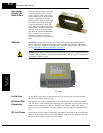
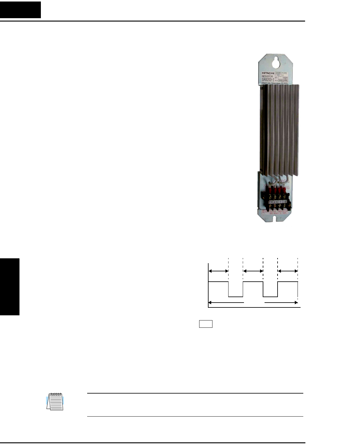
The braking resistor is the main component of a braking resistor assem-
bly, which includes an integral thermal fuse and thermally activated
alarm relay for safety. However, be careful to avoid overheating its resis-
tor. The thermal fuse and thermal relay are safeguards for extreme condi-
tions, but the inverter can maintain braking usage in a safe zone.
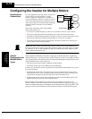
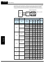
Dynamic Braking
Usage Ratio
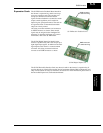
The inverter controls braking via a duty cycle
method (percent of the time braking is ON
versus total time). Parameter B090 sets the
dynamic braking usage ratio. In the graph to
the right, the example shows three uses of
dynamic braking in a 100-second period. The
inverter calculates the average percentage
usage in that time (T%). The percentage of
usage is proportional to the heat dissipated. If
T% is greater than the B090 parameter
setting, the inverter enters the Trip Mode and
turns OFF the frequency output.
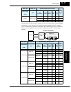
Please note the following (for SJ300–004LF/HF to SJ300–110LF/HF).
• When B090 is set for 0%, dynamic braking is not performed.
• When the T% value exceeds the limit set by B090, the inverter will trip (ending the dynamic
braking).
• The cable from the external resistor to the inverter must not exceed 5 m (16 ft.) length.
• The individual wires from the resistor to the inverter must not be bundled together.
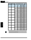
NOTE: Inverters rated 20hp (15kW) and above (SJ300–150LF/HF to SJ300–550LF/1320HFE/
1500HFU) do not include an internal braking unit. Parameters B090, B095, and B096 do not
apply to these models.
Braking
Resistor
B90
BRD
T%
t1 t2 t3 ...+++()
100 seconds
------------------------------------------
100×=
t
t1 t2 t3
ON
OFF
100s