


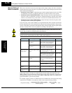
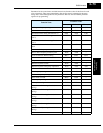

Component Descriptions
Motor Control
Accessories
5–4
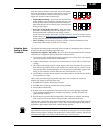
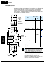
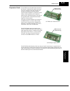
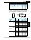
Zero-phase
Reactor (RF
Noise Filter)
Electrical noise interference may occur
on nearby equipment such as a radio
receiver. The zero-phase reactor helps
reduce radiated noise from the inverter
wiring. It can be used on the input or
output side of the inverter. The example
zero-phase reactor shown to the right
comes with a mounting bracket. The
wiring must go through the opening to
reduce the RF component of the electri-
cal noise. Loop the wires three times
(four turns) to attain the full RF filtering
effect. For larger wire sizes, place
multiple zero-phase reactors (up to
four) side-by-side for a greater filtering
effect.
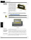
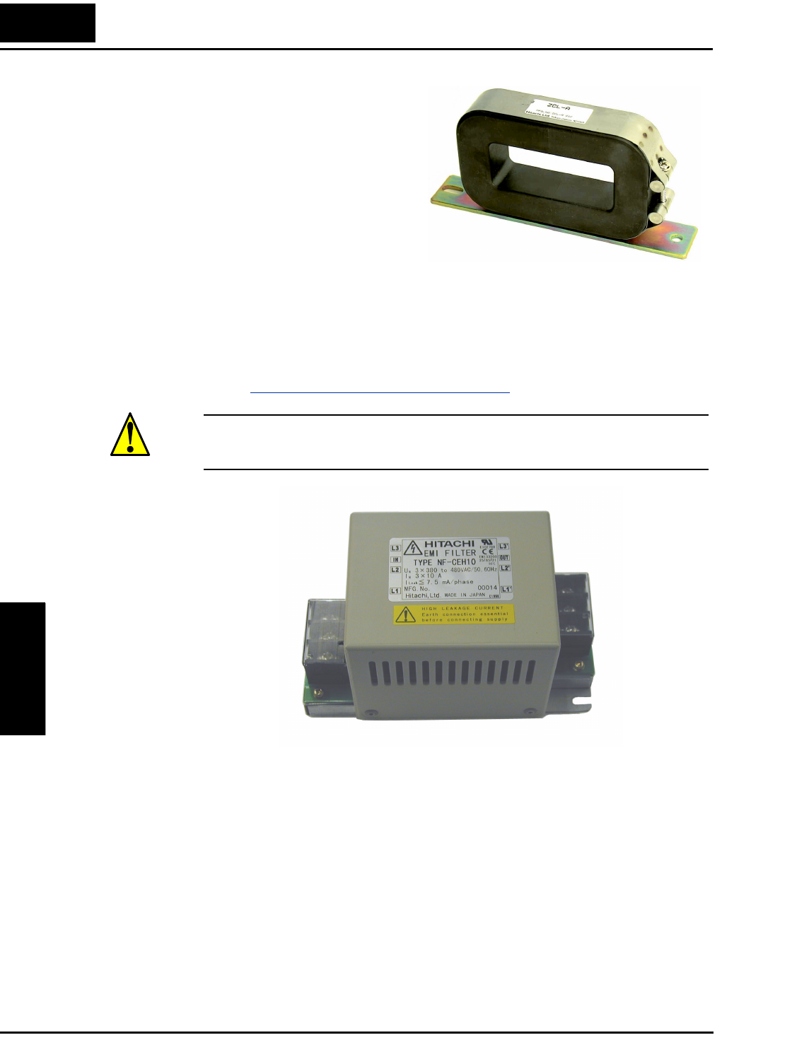
EMI Filter The EMI filter reduces the conducted noise on the power supply wiring generated by the
inverter. Connect the EMI filter to the inverter primary (input side). The NF–CEH–x series
filter is required for compliance to the EMC Class A directive (Europe) and C-TICK (Austra-
lia). See “
CE–EMC Installation Guidelines” on page D–2.
WARNING: The EMI filter has high internal leakage current from power wiring to the chassis.
Therefore, connect the chassis ground of the EMI filter before making the power connections to
avoid danger of shock or injury.
Ferrite Core To meet EMC Class B limit an optional ferrite core (FC–Hx) must be inserted between the
NF–CEHx filter (above) and the inverter.
RF Noise Filter
(Capacitive)
This capacitive filter reduces radiated noise from the main power wires in the inverter input
side. This filter is not for achieving CE compliance and is applicable only to the input side only
of the inverter. It comes in two versions—for 200V class inverters or 400V class inverters.
Please refer to the documentation that comes with the radio noise filter for installation instruc-
tions.
DC Link Choke The DC choke (reactor) suppresses harmonics generated by the inverter. It attenuates the high-
frequency components on the inverter’s internal DC bus (link). However, note that it does not
protect the diode rectifiers in the inverter input circuit.
ZCL–x
NF–CEHxx