


Using Intelligent Input Terminals
Operations
and Monitoring
4–40
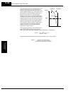
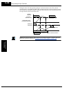
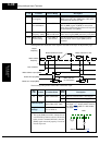
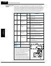
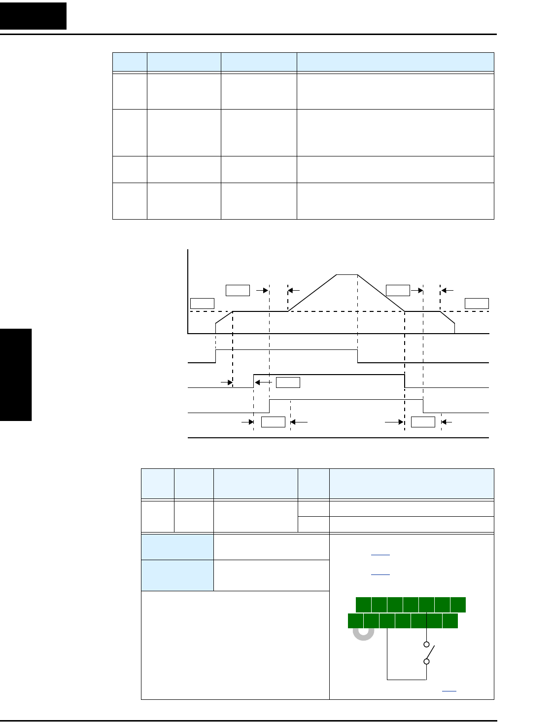
The diagram below shows the event sequence described in the steps on the previous page.
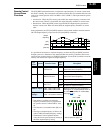
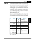
The following table pertains to the brake confirmation input.
B123 Brake wait time
for stopping
0.00 to 5.00 sec. Sets the time delay after brake confirmation signal
[BOK] turns OFF (after [BRK] turns OFF) until
decelerating the inverter to 0 Hz
B124 Brake wait time
for confirmation
0.00 to 5.00 sec. Sets the wait time for [BOK] signal after turn ON/
OFF of [BRK] signal. If [BOK] is not received
during the specified time, the inverter will trip with
an external brake error [BER].
B125 Break release
frequency setting
0.00 to 99.99 Hz /
100.0 to 400.0 Hz
Sets the frequency at which the inverter outputs the
brake release signal [BRK] after delay set by B121
B126 Brake release
current setting
0% to 200% of
rated current
Sets the minimum inverter current level above
which the brake release signal [BRK] will be
permitted
Code Function Data or Range Description
Output
frequency
Run command
Brake release output [BRK]
Brake OK input [BOK]
B122 B123
B121
B125 B125
B124
Brake release
frequency
Brake wait time to release
Brake wait time for accel Brake wait time for stop-
Brake wait time
for confirmation
B124
Brake error output [BER]
t
0
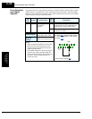
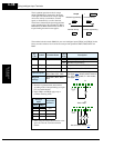
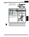
Opt.
Code
Symbol Function Name
Input
State
Description
44 BOK Brake confirmation ON Indicates external brake is not engaged
OFF Indicates external brake is engaged
Valid for inputs:
C001, C002, C003, C004,
C005, C006, C007, C008
Required
settings:
B120=01
B121 to B126 set
Notes:
• The signal [BOK] turns ON to indicate that an
external brake system has released. If external
brake control is enabled (B120=01), then the
[BOK] signal must work properly to avoid an
inverter trip event.
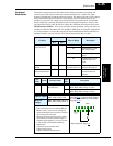
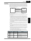
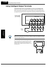
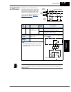
5 3 1
7 6 4 2
8
FW
TH
PLC
CM1
P24
CM1
See I/O specs on page 4–9.
Example: (Requires input configuration—
see page 3–47
. Jumper position shown is
for –xFU/-xFR models; for –xFE models,
see page 4–12
.)
BOK