


Using Intelligent Input Terminals
Operations
and Monitoring
4–12
Wiring Diagram
Conventions
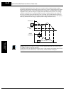
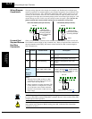
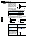
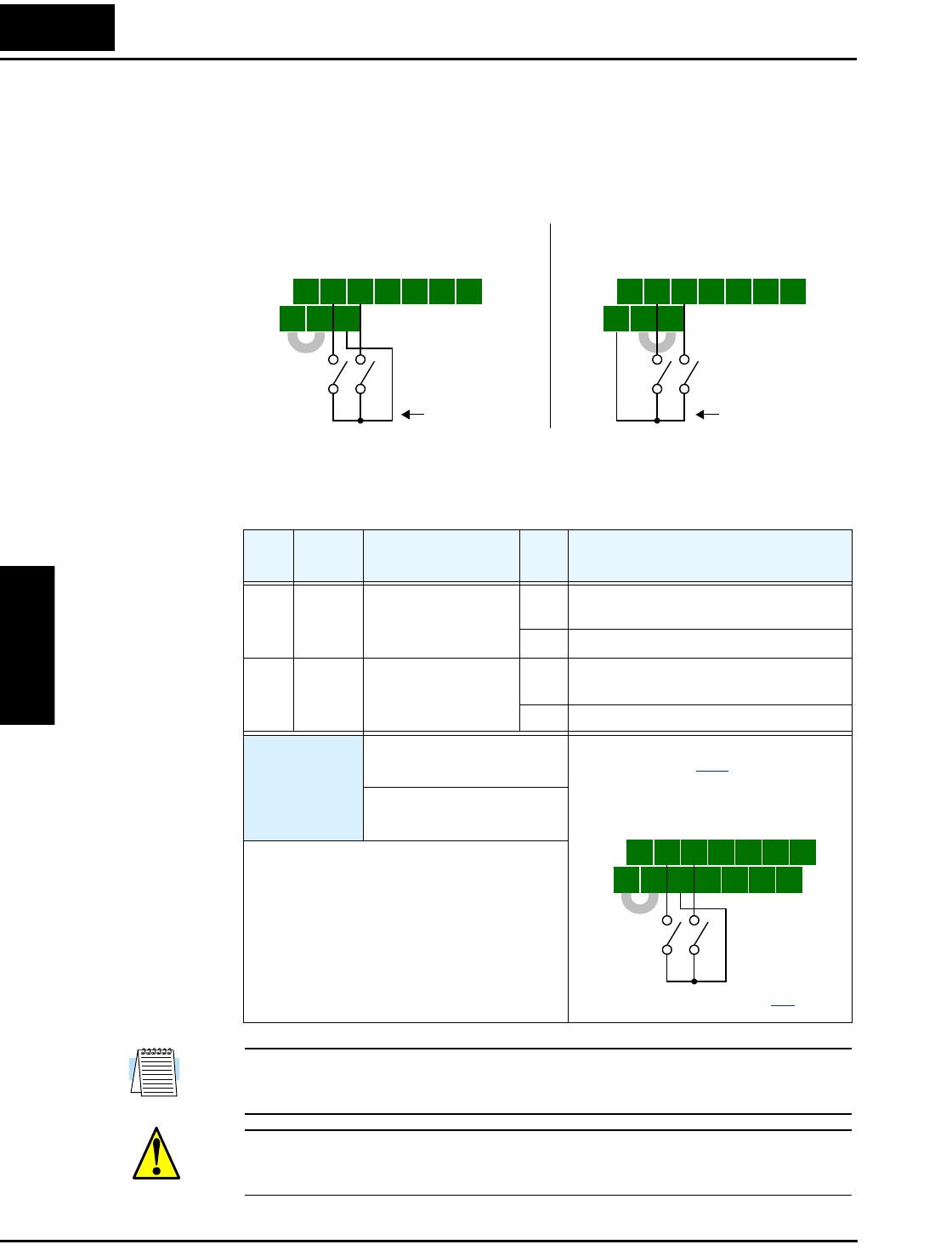
The input wiring diagrams in this chapter are examples only. Default and non-default input
terminal assignments are noted throughout; your particular assignments may be different. The
wiring diagrams show the –xFU/–xFR model default [P24]–[PLC] jumper position (U.S./Jpn
versions), as shown below on the left. The common (return) for inputs is [CM1] in this case.
The diagram on the right shows the default jumper position and example input wiring for –xFE
models (Europe version). For this case, the common (return) for inputs is [P24]. Be sure the
jumper position and return terminal used match your application wiring needs.
Forward Run/
Stop and Reverse
Run/Stop
Commands
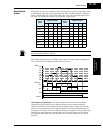
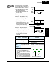
When you input the Run command via the dedicated terminal [FW], the inverter executes the
Forward Run command (high) or Stop command (low). When you input the Run command via
the programmable terminal [RV], the inverter executes the Reverse Run command (high) or
Stop command (low).
NOTE: The parameter F004, Keypad Run Key Routing, determines whether the single Run
key issues a Run FWD command or Run REV command. However, it has no effect on the [FW]
and [RV] input terminal operation.
WARNING: If the power is turned ON and the Run command is already active, the motor
starts rotation and is dangerous! Before turning power ON, confirm that the external Run
command is not active.
5 3 14 2
FW
TH
PLC
P24
CM1
5 3 14 2
FW
TH
PLC
P24
CM1
Default jumper
position [P24]–[PLC]
and wiring example
(used throughout this
chapter)
–xFU/–xFR models (U.S./Jpn versions):
–xFE models (Europe version):
Default jumper
position [PLC]–[CM1]
and wiring example
return
return
RVFW RVFW
Opt.
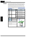
Code
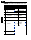
Symbol Function Name State Description
— FW Forward Run/Stop ON Inverter is in Run Mode, motor runs
forward
OFF Inverter is in Stop Mode, motor stops
01 RV Reverse Run/Stop ON Inverter is in Run Mode, motor runs
reverse
OFF Inverter is in Stop Mode, motor stops
Valid for
inputs:
C001, C002, C003, C004,
C005, C006, C007, C008
Required
settings:
A002 = 01
Notes:
• When the Forward Run and Reverse Run
commands are active at the same time, the
inverter enters the Stop Mode.
• When a terminal associated with either [FW]
or [RV] function is configured for normally
closed, the motor starts rotation when that
terminal is disconnected or otherwise has no
input voltage.
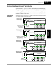
5 3 1
7 6 4 2
8
FW
TH
PLC
CM1
P24
CM1
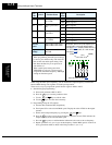
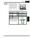
See I/O specs on page 4–9.
Example: (Default input configuration
shown—see page 3–47
. Jumper position
shown is for –xFU/-xFR models; for –xFE
models, see examples above.)
RVFW