


SJ300 Inverter
Operations
and Monitoring
4–63
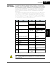
To calibrate the meter reading, generate a full-scale output (always ON) at terminal [FM]. Then
use parameter B081(gain setting from 0 to 255) to adjust the corresponding full-scale reading
of the meter. For example, when the inverter output frequency is 60 Hz, change the value of
B081 so that the meter reads 60 Hz.
TIP: When using the analog meter for monitoring, adjust the meter so it has a zero reading
when the [FM] output is zero. Then use scale factor B081 to adjust the [FM] output so the
maximum frequency in the inverter corresponds to a full-scale reading on the meter.
NOTE: The indicator accuracy after adjustment is about ±5%. Depending on the motor, the
accuracy may exceed this value.
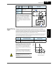
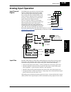
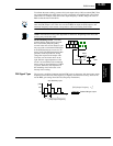
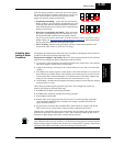
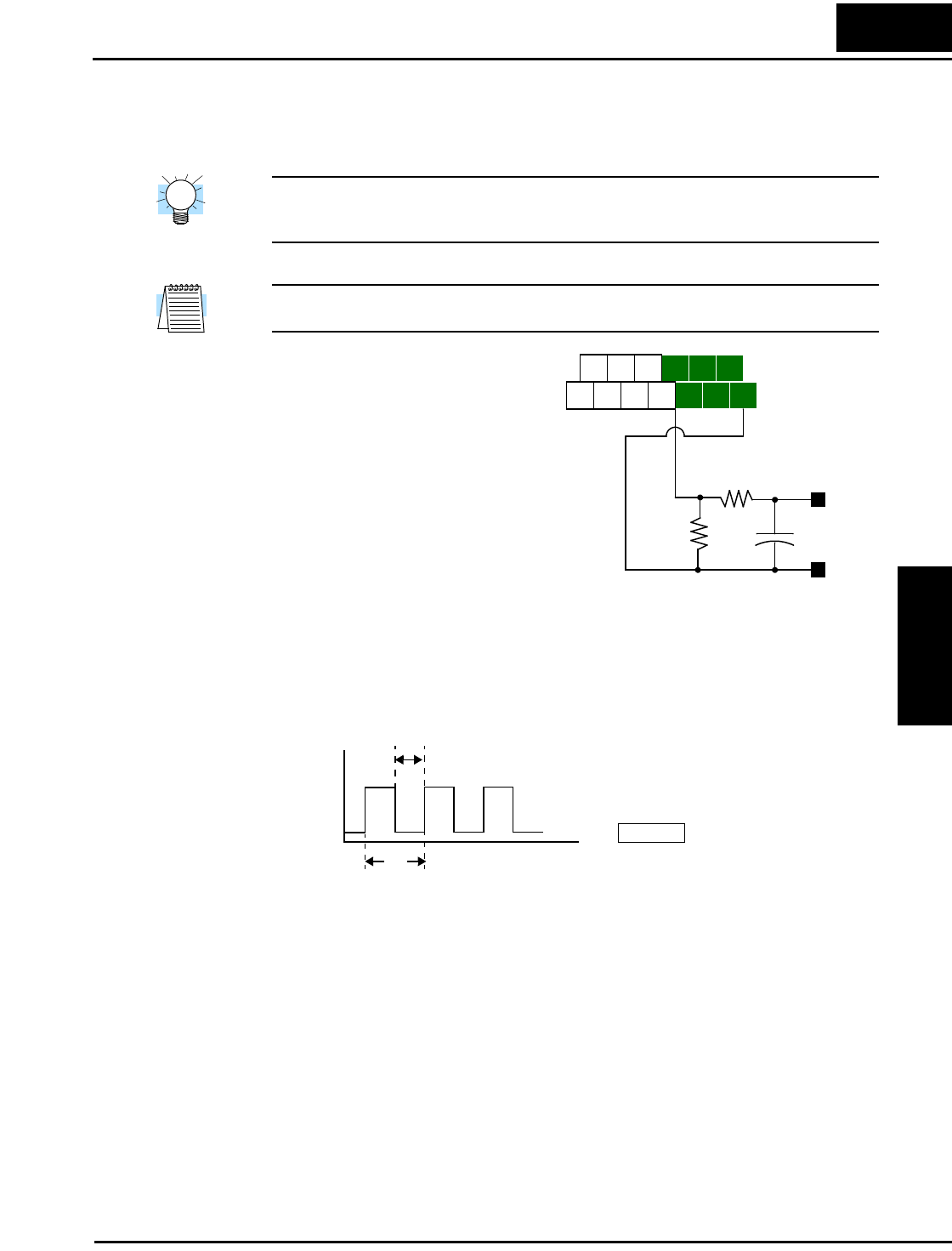
PWM Smoothing Circuit – Note that
standard analog output signals are avail-
able on terminals [AM] and [AMI],
covered in the next section. However, you
may also wish to smooth the PWM signal
at the [FM] terminal and convert it to an
analog signal. The [FM] terminal will then
generate a relatively stable DC analog
voltage that represents the output value.
To do this, use the circuit shown to the
right. Note the output impedance of the
circuit is at least 82kΩ, so the monitoring
device needs an input impedance of 1MΩ
or greater. Otherwise, the impedance of
the smoothing circuit will cause a non-
linearity in the reading.
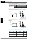
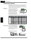
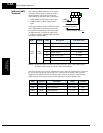
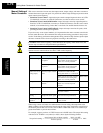
FM Signal Type The frequency-modulated output at terminal [FM] varies its frequency with the inverter output
frequency (when C027=03). This frequency is digitally controlled for accuracy, and does not
use the B081 gain setting when C027=03 (frequency modulation).
H O2
FM
AM
O OIL
FW
TH
PLC
P24
CM1
AMI
+
–
+
–
+
33kΩ
82kΩ
Volts
1µF
T
1
[FM] Output Frequency
---------------------------------------------------------=
Selects FM type output
[FM]
T
[FM] Output Frequency
1
T
---=
C027=03
t
10V
0V
50% fixed duty cycle