


Communications Protocol
Appendix B
B–8
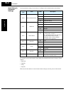
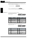
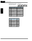
The arrangement of the terminal assignment data permits you to assign all inputs in a single
command. The example below shows a transmission to the inverter at address Node 1 to set the
Forward command, Multi-speed 1 and Multi-speed 2.
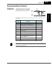
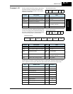
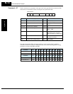
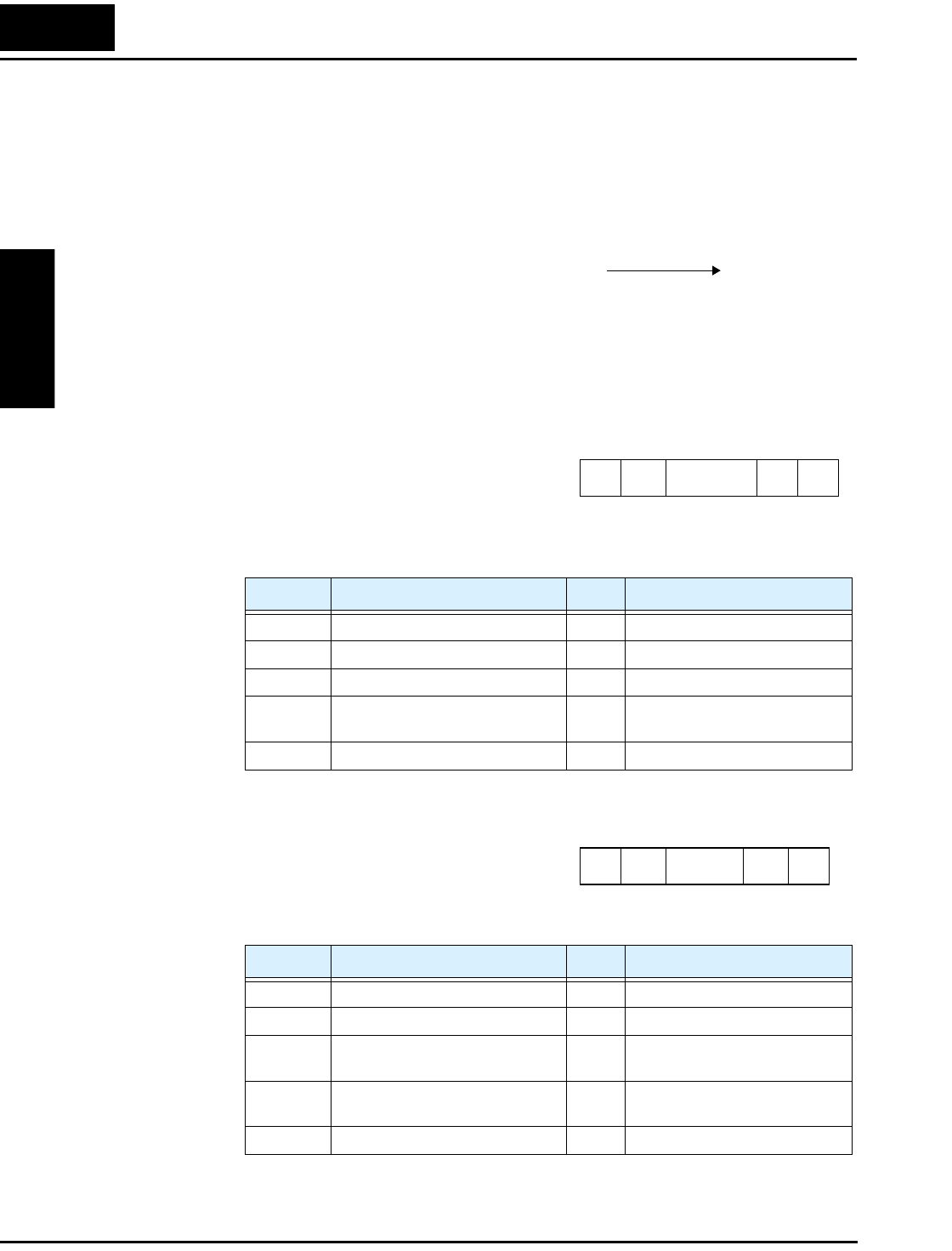
Command – 03 The 03 command reads the monitor data as a single block.
The frame format of command 03 follows the
diagram and specification table. The transmit
frame has no data field.
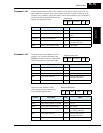
The receive frame has a 104-byte data field,
containing values for 13 items.
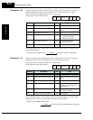
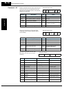
(STX) | 01 | 02 | 0x000000000000000D | (BCC) | (CR)
to ASCII
02 | 30 31 | 30 31 | 30 30 30 30 30 30 30 30 30 30 30 30 30 30 30 68 | 30 35 | 0D
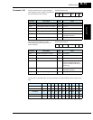
0x0000000000000001
+ 0x0000000000000004
+ 0x0000000000000008
= 0x000000000000000D
Sum the three data strings:
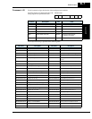
Element Description Size Value
STX Control code (STart of TeXt) 1 byte STX (0x02)
Node Node (station) address of inverter 2 bytes 01 to 32
Command Transmission command 2 bytes 03
BCC Block check sum code 2 bytes Exclusive OR of Node,
Command, and Data
[CR] Control code (carriage return) 1 byte [CR] (0x0D)
Element Description Size Value
STX Control code (STart of TeXt) 1 byte STX (0x02)
Node Node (station) address of inverter 2 bytes 01 to 32
Data Transmission data 104
bytes
(see next table)
BCC Block check sum code 2 bytes Exclusive OR of Node,
Command, and Data
[CR] Control code (carriage return) 1 byte [CR] (0x0D)
STX Node Command BCC [CR]
Transmit frame format
STX
Node Data BCC [CR]
Receive frame format