


SJ300 Inverter
Configuring Drive
Parameters
3–5
Operational
Modes
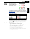
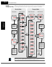
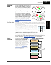
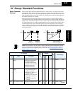
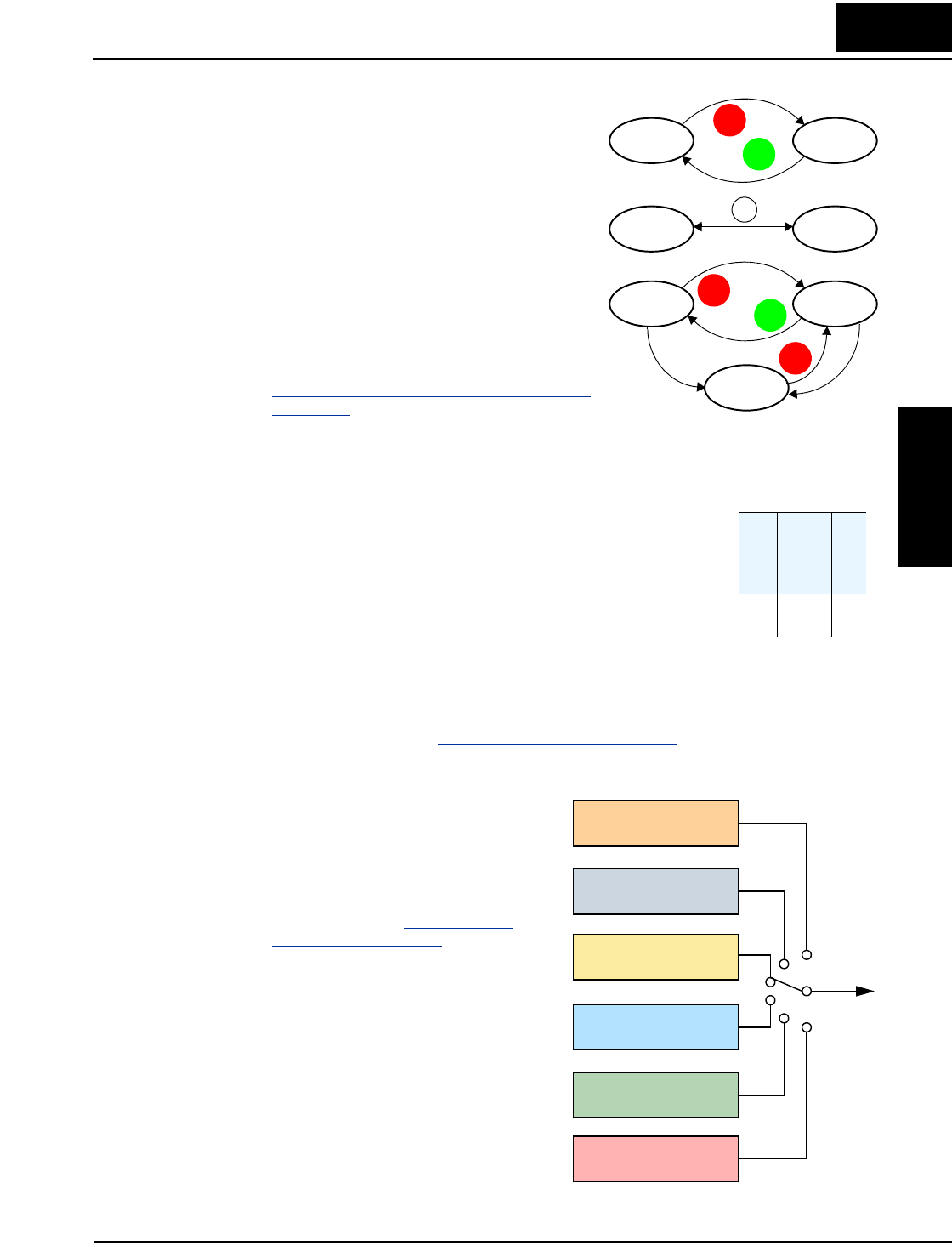
The RUN and PGM LEDs tell just part of the story;
Run Mode and Program Modes are independent
modes, not opposite modes. In the state diagram to
the right, Run alternates with Stop, and Program
Mode alternates with Monitor Mode. This is a very
important ability, for it shows that a technician can
approach a running machine and change some
parameters without shutting down the machine.
The occurrence of a fault during operation will
cause the inverter to enter the Trip Mode as shown.
An event such as an output overload will cause the
inverter to exit the Run Mode and turn OFF its
output to the motor. In the Trip Mode, any request
to run the motor is ignored. You must clear the
error by pressing the Stop/Reset switch. See
“
Monitoring Trip Events, History, & Conditions”
on page 6–5.
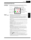
Run Mode Edits The inverter can be in Run Mode (inverter output is controlling motor) and still allow you to
edit certain parameters. This is useful in applications that must run continuously, yet need some
inverter parameter adjustment.
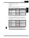
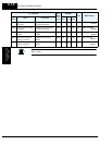
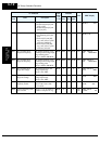
The parameter tables in this chapter have a column titled “Run Mode
Edit.” An Ex mark ✘ means the parameter cannot be edited; a Check
mark ✔ means the parameter can be edited. You’ll notice in the table
example to the right the two adjacent marks: “✘ ✔”. The two marks
(that can also be “✘ ✘” or “✔ ✔”) correspond to these levels of access
to editing:
• Low-access level to Run Mode edits (indicated by left-most mark)
• High-access level to Run Mode edits (indicated by right-most mark)
The Software Lock Setting (parameter B031) determines the particular access level that is in
effect during Run Mode and access in other conditions, as well. It is the responsibility of the
user to choose a useful and safe software lock setting for the inverter operating conditions and
personnel. Please refer to “
Software Lock Mode” on page 3–36 for more information.
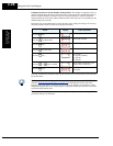
Control
Algorithms
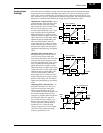
The motor control program in the SJ300
inverter has several sinusoidal PWM
switching algorithms. The intent is that you
select the best algorithm for the motor
characteristics in your application. Each
algorithm generates the frequency output in
a unique way. Once configured, the
algorithm is the basis for other parameter
settings as well (see “
Torque Control
Algorithms” on page 3–14). Therefore,
choose the best algorithm early in your
application design process.
RUN
STOP
RESET
FUNC.
Run Stop
Monitor Program
RUN
STOP
RESET
STOP
RESET
Run Stop
Fault
Tri p
Fault
Run
Mode
Edit
Lo Hi
✘ ✔
Output
V/f control,
constant torque
V/f control,
variable torque
V/f control, free-
setting curve
Inverter Control Algorithms
Sensorless vector
(SLV) control
SLV control,
0Hz domain
Vector control with
sensor