


Using Intelligent Input Terminals
Operations
and Monitoring
4–24
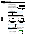
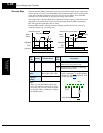
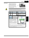
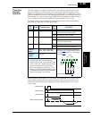
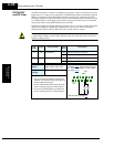
In the previous timing diagram, when the motor has been started across the line, Mg2 is
switched OFF and Mg3 is switched ON. With the Forward command to the inverter already
ON, the [CS] terminal is switched ON and relay Mg1 contacts close. The inverter will then read
the motor RPM (frequency matching). When the [CS] terminal is switched OFF, the inverter
applies the Retry wait time before motor restart parameter (B003).
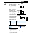
Once the delay time has elapsed the inverter will then start and match the frequency (if greater
than the threshold set by B007). If the ground fault interrupter breaker (GFI) trips on a ground
fault, the bypass circuit will not operate the motor. When an inverter backup is required, take
the supply from the bypass circuit GFI. Use control relays for [FW], [RV], and [CS].
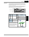
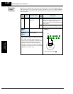
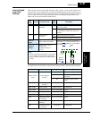
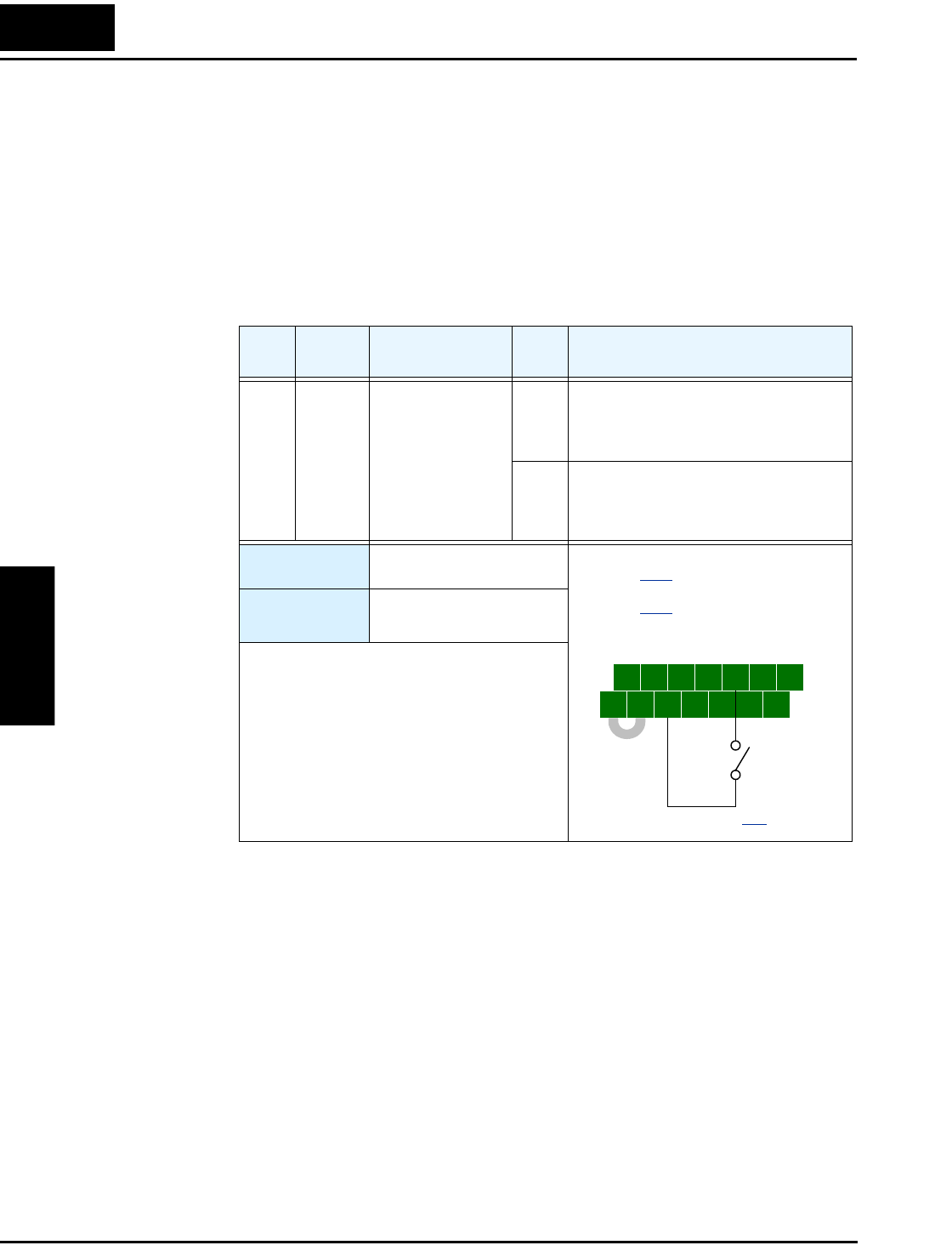
The commercial power source switching function requires you to assign [CS] to an intelligent
input terminal, using option code 14.
Opt.
Code
Symbol Function Name
Input
State
Description
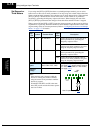
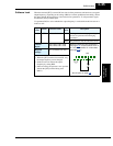
14 CS Commercial Power
Change
ON OFF-to-ON transition signals the inverter
that the motor is already running at
powerup (via bypass), thus suppressing
the inverter’s motor output in Run Mode
OFF ON-to-OFF transition signals the inverter
to apply a time delay (B003), frequency
match its output to existing motor speed,
and resume normal Run Mode operation
Valid for inputs:
C001, C002, C003, C004,
C005, C006, C007, C008
Required
settings:
B003, B007
Notes:
• If an over-current trip occurs during frequency
matching, extend the retry wait time B003.
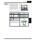
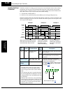
5 3 1
7 6 4 2
8
FW
TH
PLC
CM1
P24
CM1
See I/O specs on page 4–9.
Example: (Requires input configuration—
see page 3–47
. Jumper position shown is
for –xFU/-xFR models; for –xFE models,
see page 4–12
.)
CS