


SJ300 Inverter
Appendix B
B–15
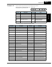
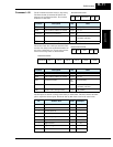
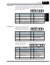
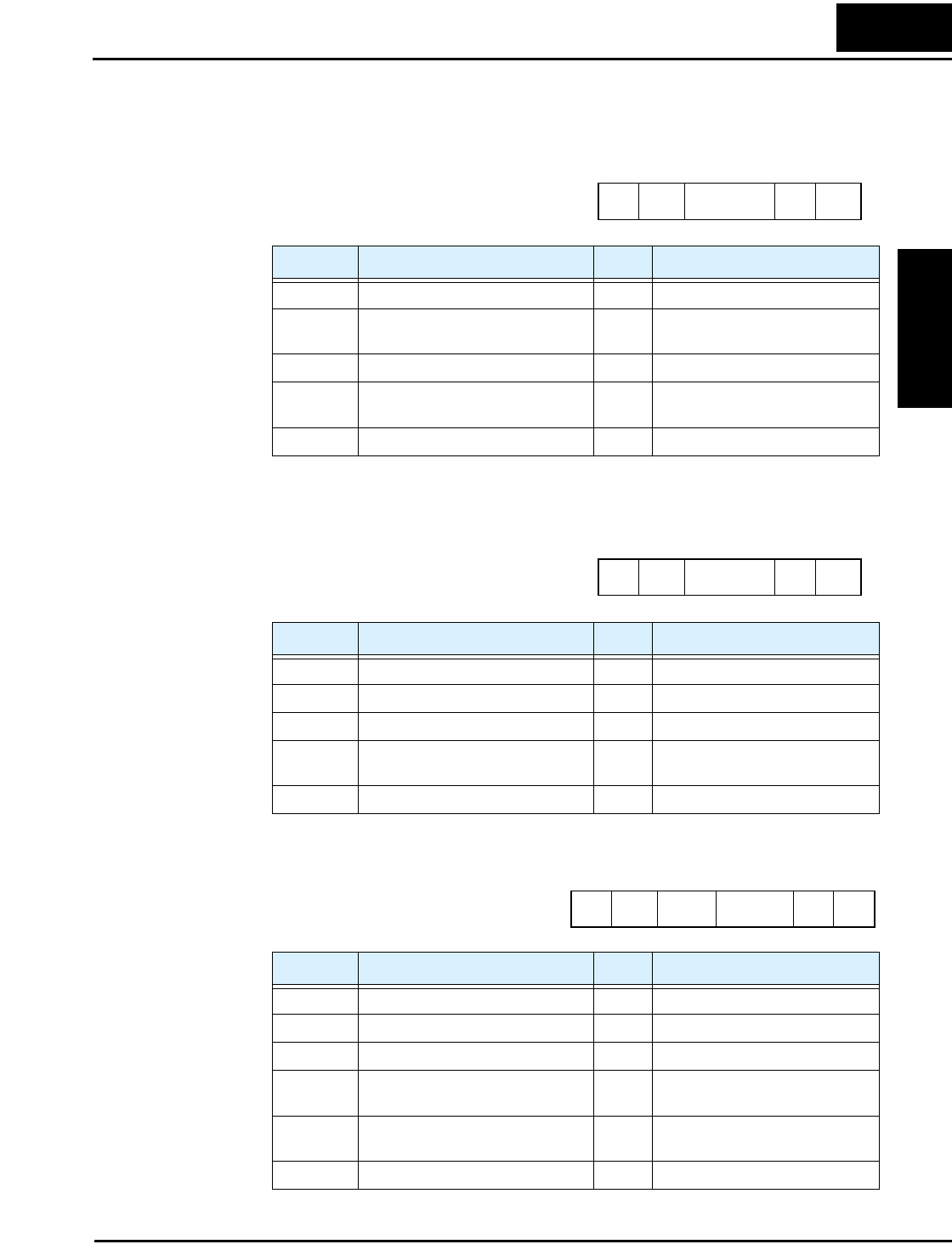
Command – 08 The 08 command initializes the inverter parameters to the factory default values. First, you
must set B84 (use command 07) to specify whether you want to clear the trip history at the
same time. Also, set B85 to specify the country code for the initialization (use command 07).
The frame format of command 08 follows the
diagram and specification table.
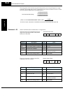
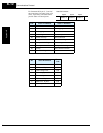
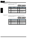
Command – 09 The 09 command verifies whether or not it is
possible to set a particular parameter in the
EEPROM. The frame format of command 08
follows the diagram and specification table.
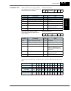
The receive frame includes an ACK
(acknowledge) character, followed by a
2-byte data field with the result.
Element Description Size Value
STX Control code (STart of TeXt) 1 byte STX (0x02)
Node Node (station) address of inverter 2 bytes 01 to 32, and FF (broadcast to all
nodes)
Command Transmission command 2 bytes 08
BCC Block check sum code 2 bytes Exclusive OR of Node,
Command, and Data
[CR] Control code (carriage return) 1 byte [CR] (0x0D)
STX Node Command BCC [CR]
Frame format
Element Description Size Value
STX Control code (STart of TeXt) 1 byte STX (0x02)
Node Node (station) address of inverter 2 bytes 01 to 32
Command Transmission command 2 bytes 09
BCC Block check sum code 2 bytes Exclusive OR of Node,
Command, and Data
[CR] Control code (carriage return) 1 byte [CR] (0x0D)
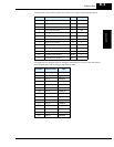
Element Description Size Value
STX Control code (STart of TeXt) 1 byte STX (0x02)
Node Node (station) address of inverter 2 bytes 01 to 32
ACK Control code (ACKnowledge) 1 byte ACK (0x06)
Data Parameter value 2 bytes 00 = setting not allowed,
01 = setting is allowed
BCC Block check sum code 2 bytes Exclusive OR of Node,
Command, and Data
[CR] Control code (carriage return) 1 byte [CR] (0x0D)
STX Node Command BCC [CR]
Transmit frame format
STX
Node ACK Data BCC [CR]
Receive frame format