


SJ300 Inverter
Operations
and Monitoring
4–27
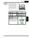
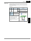
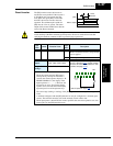
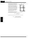
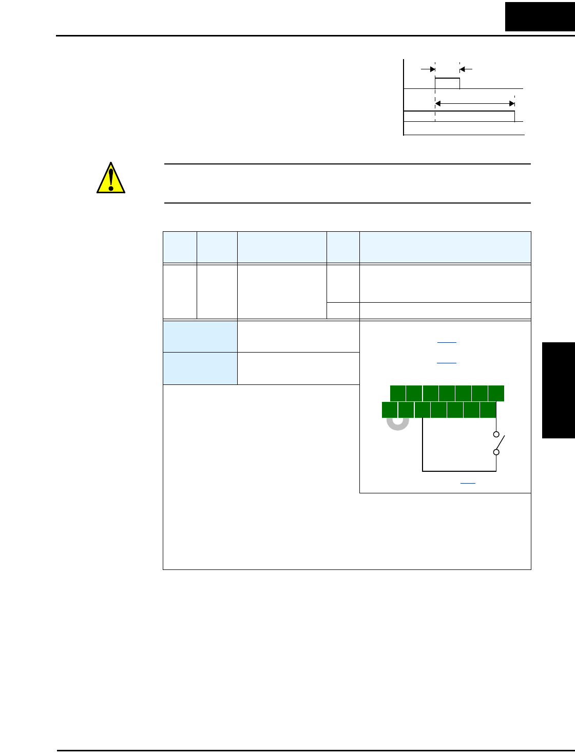
Reset Inverter The [RS] terminal causes the inverter to
execute the reset operation. If the inverter is
in Trip Mode, the reset cancels the Trip
state. When the signal [RS] is turned ON
and OFF, the inverter executes the reset
operation. The minimum pulse width for
[RS] must be 12 ms or greater. The alarm
output will be cleared within 30 ms after the
onset of the Reset command.
WARNING: After the Reset command is given and the alarm reset occurs, the motor will
restart suddenly if the Run command is already active. Be sure to set the alarm reset after
verifying that the Run command is OFF to prevent injury to personnel.
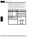
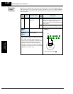
Opt.
Code
Symbol Function Name
Input
State
Description
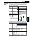
18 RS Reset Inverter ON The motor output is turned OFF, the Trip
Mode is cleared (if it exists), and powerup
reset is applied
OFF Normal power-on operation
Valid for
inputs:
C001, C002, C003, C004,
C005, C006, C007, C008
Required
settings:
B003, B007, C102, C103
Notes:
• When the control terminal [RS] input is
already ON at powerup for more than 4
seconds, the remote operator display is “R-
ERROR COMM<2>” (the display of the
digital operator is – – – –). However, the
inverter has no error. To clear the digital
operator error, turn OFF the terminal [RS]
input and press one of the operator keys.
• The active edge (leading or trailing) of the [RS] signal is determined by the setting of
C102.
• A terminal configured with the [RS] function can only be configured as a normally open
contact. The terminal cannot be used in the normally closed contact state.
• When input power is turned ON, the inverter performs the same reset operation as it does
when a pulse on the [RS] terminal occurs.
[RS]
Alarm output
t
12 ms
minimum
approx. 30 ms
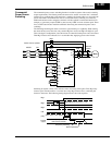
5 3 1
7 6 4 2
8
FW
TH
PLC
CM1
P24
CM1
See I/O specs on page 4–9.
Example: (Default input configuration
shown—see page 3–47
. Jumper position
shown is for –xFU/-xFR models; for –xFE
models, see page 4–12
.)
RS