


Analog Output Operation
Operations
and Monitoring
4–64
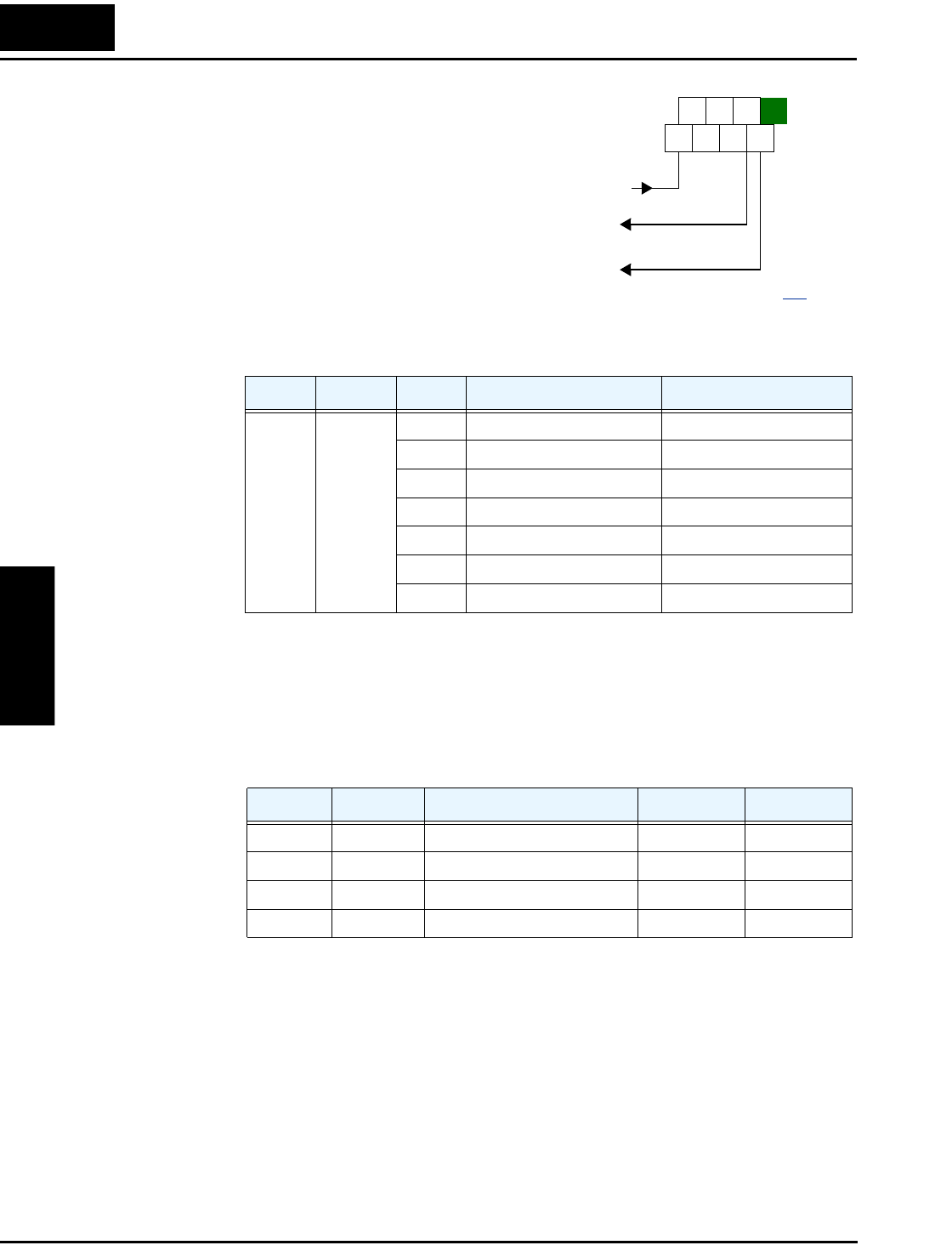
[AM] and [AMI]
Terminals
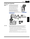
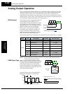
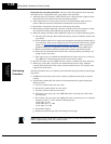
The [AM] and [AMI] terminals provide signals
to monitor various inverter parameters such as
output frequency, output current, and torque.
The terminals provide these analog signal types:
• [AM] terminal: 0–10V analog output signal
• [AMI] terminal: 4–20mA analog output
signal
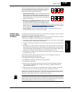
These signals both use the [L] terminal for signal
return. Eight different inverter parameters may
be monitored independently at either the [AM]
or [AMI] terminal, as listed in the table below.
Use C028 to configure terminal [AM], and C029
to configure terminal [AMI].
Note 1: Display of torque is possible only during sensorless vector control, 0Hz domain
sensorless vector control, and vector control with feedback
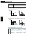
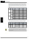
The analog signals may need some adjustment for gain or offset to compensate for variances in
the system. For example, the signals may drive a panel meter and require a full-scale gain
adjustment. The table below lists the function codes and their descriptions. The [AM] and
[AMI] terminals have separate gain and offset adjustments. Note the default values.
Func. Terminal Code Description Full Scale Value
C028 /
C029
[AM] /
[AMI]
00 Output frequency 0 – Max. frequency (Hz)
01 Output current 0 – 200%
02 Output torque *1 0 – 200%
04 Output voltage 0 – 100%
05 Input electric power 0 – 200%
06 Thermal load ratio 0 – 100%
07 LAD frequency 0 – Max. frequency (Hz)
Func. Terminal Description Range Default
B080 [AM] Gain adjustment 0 – 255 180
C086 [AM] Offset Adjustment 0.0 – 10.0V 0.0V
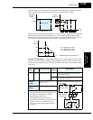
C087 [AMI] Gain adjustment 0 – 255 80
C088 [AMI] Offset Adjustment 0.0 – 20.0mA 0.0mA
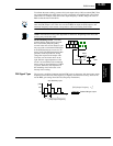
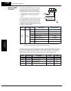
H O2
FM
AM
O OIL
AMI
A GND
See I/O specs on page 4–9.
0–10V analog output
4–20mA analog output