Using Intelligent Input Terminals
Operations
and Monitoring
4–16
Jogging
Command
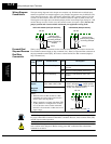
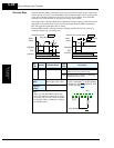
The Jog input [JG] is used to command the
motor to rotate slowly in small increments
for manual operation. The speed is limited
to 10 Hz. The frequency for the jogging
operation is set by parameter A038. Jogging
does not use an acceleration ramp. There-
fore setting the jogging frequency A038 too
high will cause inverter tripping.
A jog command may arrive while the motor
is running. You can program the inverter to
either ignore or respond to a jog command
in this case by using function A039. The
type of deceleration used to end a motor jog
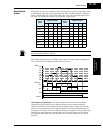
is also selectable by programming function A039. Six jog mode options are defined below:
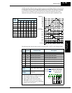
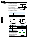
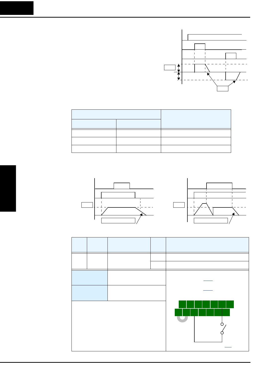
In the left example diagram below, the Jog command is ignored. In the right example diagram,
a jog command interrupts a Run mode operation. However, if the Jog command turns ON
before the [FW] or [RV] terminal turns ON, the inverter output turns OFF.
Jogging During Motor Operation
Jog Deceleration Method
Disabled, A039= Enabled, A039=
00 03 Free-run stop (coasting)
01 04 Deceleration (normal level) and stop
02 05 Use DC braking and stop
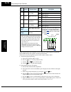
Opt.
Code
Symbol Function Name
Input
State
Description
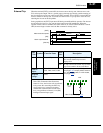
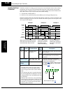
06 JG Jogging ON Enters Jog Mode if enabled (see above)
OFF Jog is OFF
Valid for
inputs:
C001, C002, C003, C004,
C005, C006, C007, C008
Required
settings:
A002= 01, A038 > B082,
A038 > 0, A039=00 to 05
Notes:
• Jogging is not performed when the value of
A038 jogging frequency is smaller than the
start frequency B082 or the
value is 0 Hz.
• Be sure to turn ON [FW] or [RV] after the
[JG] input turns ON for a jog operation.
• When setting A039 to 02 or 05, you must also
set the DC braking parameters.
[JG]
[FW]
Jog decel type
[RV]
Output
frequency
A038
A039
t
[JG]
[FW]
Output
frequency
A039=00, 01, 02
Decelerating stop (00) shown
[JG]
[FW]
Output
frequency
A039=03, 04, 05
Free-run stop (05) shown
A038 A038
t
t
5 3 1
7 6 4 2
8
FW
TH
PLC
CM1
P24
CM1
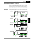
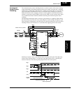
See I/O specs on page 4–9.
Example: (Default input configuration
shown—see page 3–47. Jumper position
shown is for –xFU/-xFR models; for –xFE
models, see page 4–12
.)
JG


