


Setting Motor Constants for Vector Control
Operations
and Monitoring
4–70
Manual Setting of
Motor Constants
With vector control, the inverter uses the output current, output voltage, and motor constants to
estimate the motor torque and speed. It is possible to achieve a high starting torque and accurate
speed control at low frequency
• Sensorless Vector Control – improved torque control at output frequencies down to 0.5 Hz.
Use A044=03 (1st motor) or A244=03 (2nd motor) to select sensorless vector control.
• Sensorless Vector Control, 0Hz Domain – improved torque control at output frequencies
from 0 to 2.5 Hz. Use A044=04 (1st motor) or A244=04 (2nd motor). For this vector control
method, we recommend using a motor that is one frame size smaller than the inverter size.
• Sensorless Vector Control with Feedback – improved torque control at all speeds, while
providing the most accurate speed regulation
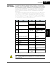
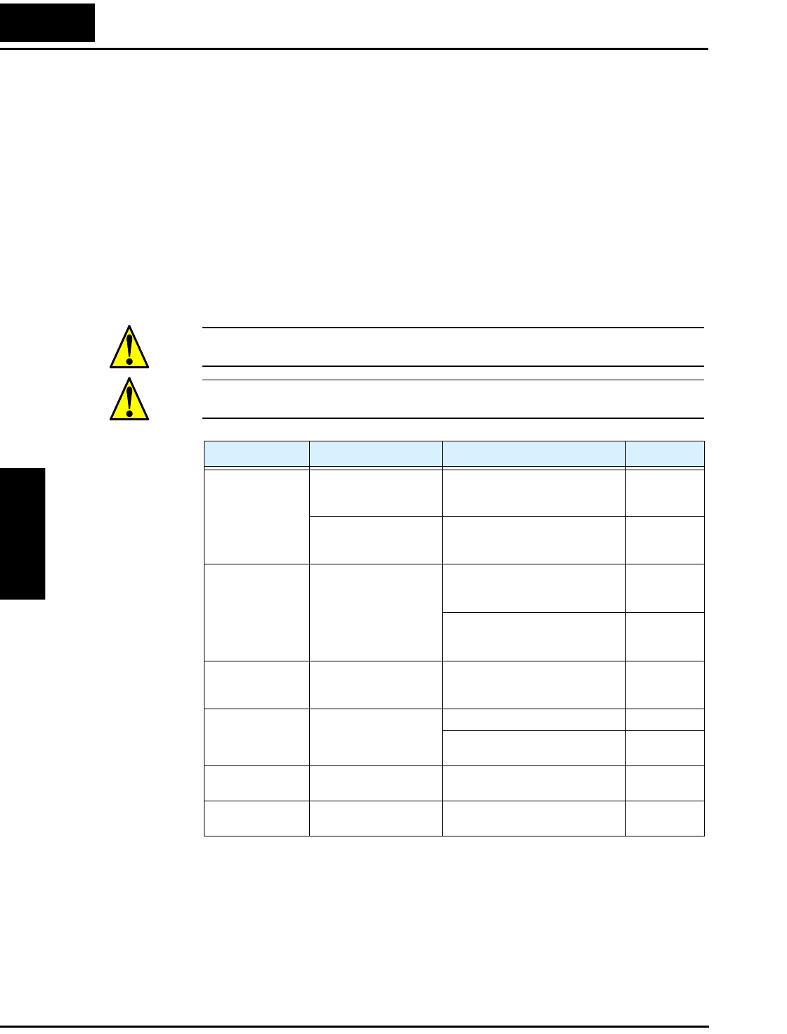
If you do use any vector control methods, it is important that the motor constants stored in the
inverter match the motor. We recommend first using the auto-tuning procedure in the previous
section. If satisfactory performance through auto-tuning cannot be fully obtained, please adjust
the motor constants for the observed symptoms according to the table below.
CAUTION: If the inverter capacity is more than twice the capacity of the motor in use, the
inverter may not achieve its full performance specifications.
CAUTION: You must use a carrier frequency of more than 2.1kHz. The inverter cannot
operate in vector control mode at less than 2.1 kHz carrier frequency.
When using a motor one frame size smaller than the inverter rating, the torque limit value
(B041 to B044) is from the following formula and the value of the actual motor torque limit is
calculated by the formula. Do not set a value in B041 to B044 that results in an actual torque
greater than 200% or you risk motor failure.
For example, suppose you have a 0.75kW inverter and a 0.4kW motor. The torque limit setting
value that is for T=200% is set (entered) as 106%, shown by the following formula:
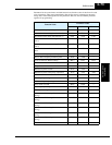
Operation Status Symptom Adjustment Parameter
Powered running When the speed deviation
is negative
Slowly increase the motor constant
R2 in relation to auto-tuning data,
within 1 to 1.2 times preset R2
H021 / H221
When the speed deviation
is positive
Slowly decrease the motor constant
R2 in relation to auto-tuning data,
within 0.8 to 1 times preset R2
H021 / H221
Regeneration
(status with a decel-
erating torque)
When low frequency (a
few Hz) torque is insuffi-
cient
Slowly increase the motor speed
constant R1 in relation to auto-
tuning data within 1 to 1.2 times R1
H020 / H220
Slowly increase the motor constant
IO in relation to auto-tuning data,
within 1 to 1.2 times preset IO
H023 / H223
During acceleration A sudden jerk at start of
rotation
Increase motor constant J slowly
within 1 to 1.2 times the preset
constant
H024 / H224
During deceleration Unstable motor rotation Decrease the speed response H05, H205
Set motor constant J smaller than
the preset constant
H024, H224
During torque
limiting
Insufficient torque during
torque limit at low speed
Set the overload restriction level
lower than the torque limit level
B021,
B041 to B044
At low-frequency
operation
Irregular rotation Set motor constant J larger than the
preset constant
H024, H244
Torque limit setting
Actual torque limit Motor capacity
×
Inverter capacity
--------------------------------------------------------------------------
200% 0.4kW×
0.75kW
-------------------------------
106%===