


SJ300 Inverter
Operations
and Monitoring
4–71
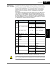
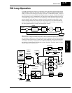
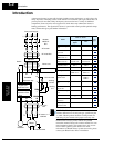
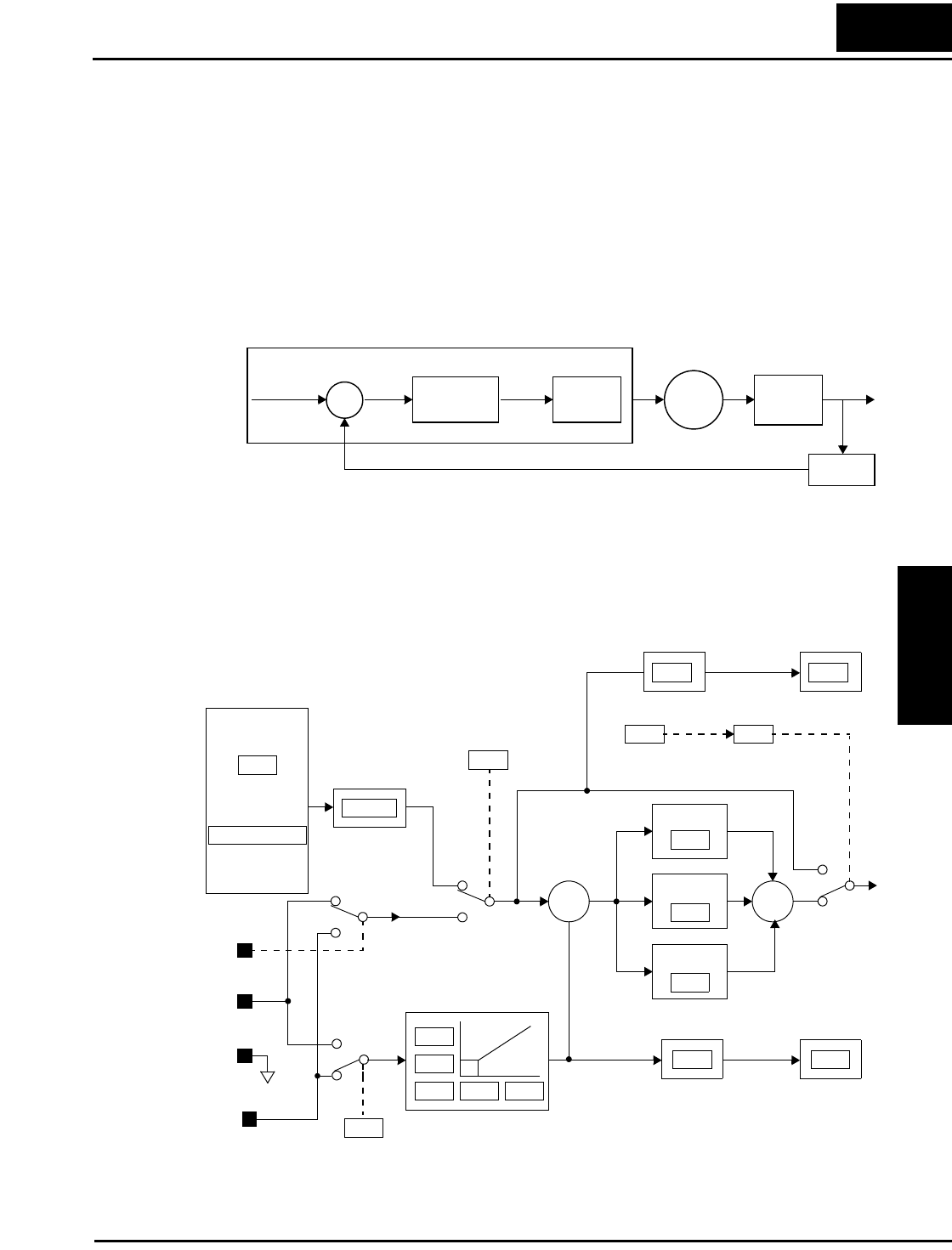
PID Loop Operation
In standard operation, the inverter uses a reference source selected by parameter A001 for the
output frequency, which may be a fixed value (F001), a variable set by the front panel potenti-
ometer, or value from an analog input (voltage or current). To enable PID operation, set A071 =
01. This causes the inverter to calculate the target frequency, or setpoint. An optional intelligent
input assignment (code 23), PID Disable, will temporarily disable PID operation when active.
A calculated target frequency can have a lot of advantages. It lets the inverter adjust the motor
speed to optimize some other process variable of interest, potentially saving energy as well.
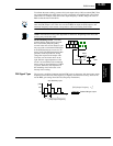
Refer to the figure below. The motor acts upon the external process. To control that external
process, the inverter must monitor the process variable. This requires wiring a sensor to either
the analog input terminal [O] (voltage) or terminal [OI] (current).
When enabled, the PID loop calculates the ideal output frequency to minimize the loop error.
This means we no longer command the inverter to run at a particular frequency, but we specify
the ideal value for the process variable. That ideal value is called the setpoint, and is specified
in the units of the external process variable. For a pump application it may be gallons/minute,
or it could be air velocity or temperature for an HVAC unit. Parameter A075 is a scale factor
that relates the external process variable units to motor frequency. The figure below is a more
detailed diagram of the PID function.
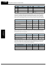
∑
PID
Calculation
ErrorSetpoint
SP
PV
Freq.
Inverter
Output
Motor
External
Process
Sensor
Process Variable (PV)
Inverter
Analog input
Monitor
P gain
I gain
D gain
∑
Analog input scaling
∑
Voltage
O
OI
L
Current
A GND
PID V/I
input select
Process Variable
(Feedback)
Scale factor
Frequency
setting
Scale factor
Setpoint
(Target)
Scale factor
reciprocal
Multi-speed
settings
Standard
setting
Frequency
source select
Potentiometer
on keypad
Error
[AT]
V/I input
select
PV
SP
A001
A075 F001
F001
1/A075
A020 to A035
A072
A073
A075 D004
A074
A076
A011
A015
A012
A013 A014
A071
PID Enable
C023
PID Disable
optional
intelligent input
PID
Normal