ACU-RITE 3500i 279
10.1 CAM Programming
CAM Mode Screen
In CAM Mode the CNC displays the CAM Mode screen.
The CAM Mode screen Displays three groups of icons, and one
Toolbar on the left:
Geometry Toolbar menu 2.
Modifying Toolbar menu 3.
Viewing Toolbar menu 4.
Vertical button bar example 5. The Side tool bar changes depending
on the geometry tool selected.
Activating CAM Mode
To activate CAM Mode:
In Manual Data Input Mode, select the Program
Management button to activate the Program Directory
button.
Touch the New Program button to create a new
program.
Select the CAM button.
The CAM screen activates.
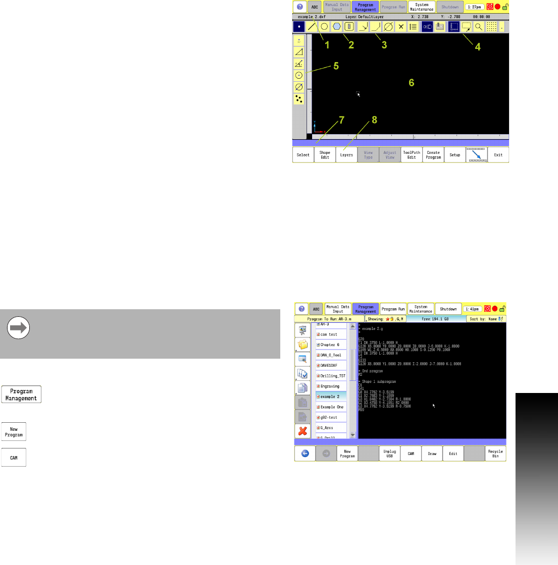
1
Status Bar: Displays the program name, active layer and mouse
cursor position, and estimated machining time.
2
Main Toolbar (Section 1): Geometry Tools, Modifying Tools,
Viewing Tools.
3 Main Toolbar (Section 2): Modifying Tools.
4 Main Toolbar (Section 3): Viewing Tools.
5 Side Toolbar: Displays options for Geometry Tools.
6 Graphics Display Area: Displays geometry, shape and Tool Paths.
7
Message, and Prompt Display: Displays messages or prompts
user for input.
8
Buttons: Offer various functionality based on tool type or button
chosen.
CAM must be used with a program. This can be an
existing program or a new program. Care must be taken
when using an existing program, CAM will overwrite the
program.


