


330 10 CAM: Programming
10.1 CAM Programming
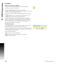
CAM Example 1
Creating basic geometry for tool path usage. In this exercise a pocket
slot will be created, and completing the slot will require the use of a
tool path for clean up. The slot will be .500” wide, by 1.000” long on
center, and .375” deep. A .375” diameter end mill will be used.
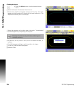
Exercise One:
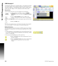
The first steps are to set up a new program for this exercise.
In Manual Data Input Mode, select the PROGRAM
MANAGEMENT button to activate the Program Directory
button.
Touch the New Program button to create a new
program, and type in the new name of the program.
Touch the G-Code/ISO box as the new program type, and then touch
Ok.
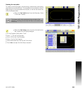
Select the CAM button.
With the new program set up, and named, the steps in this program
can now be created. The first step is to create the geometry.
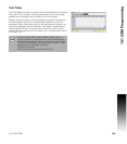
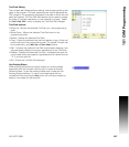
Defining Geometry:
Geometry items are the basic element of CAM programming. Shapes
are created from geometry, and tool paths are generated from these
shapes.
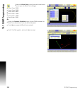
To define geometry, the applicable button from the Geometry Tools
in the main Toolbar will need to be selected. See "Geometry Toolbar
buttons:" on page 280.
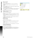
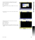
In this exercise the Circle button will be used first.
Select the Circle button from the Geometry Tools in
the main Toolbar.
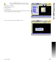
Select the Create Circle button for the method to be
used to define the geometry from the vertical
Toolbar.