


Polycom RMX 2000/4000 Administrator’s Guide
12-51
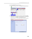
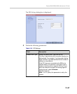
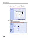
10 Define the following parameters:
11 Click OK.
The new range is added to the Dial-in Phone Numbers table.
12 Optional. Repeat steps 8 to 10 to define additional dial-in ranges.
13 Enter the MCU CLI (Calling Line Identification).
In a dial-in connections, the MCU CLI indicates the MCU’s number
dialed by the participant. In a dial-out connection, indicates the MCU
(CLI) number as seen by the participant
14 Click Save & Continue.
After clicking Save & Continue, you cannot use the Back button to
return to previous configuration dialog boxes.
The ISDN/PSTN Network Service is created and confirmed.
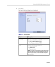
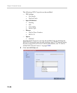
15 Click OK to continue the configuration.
The Spans dialog box opens displaying the following read-only fields:
— ID – The connector on the ISDN/PSTN card (PRI1 - PRI12).
— Slot – The MPM board that the ISDN/PSTN card is connected to
(1 or 2)
— Service – The Network Service to which the span is assigned, or
blank if the span is not assigned to a Network Service
— Clock Source – Indicates whether the span acts as a clock source,
and if it does, whether it acts as a Primary or Backup clock
source. The first span to synchronize becomes the primary clock
source.
— State – The type of alarm: No alarm, yellow alarm or red alarm.
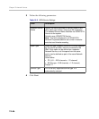
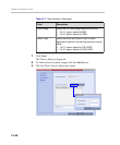
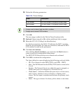
Table 12-8 Phones Settings
Field Description
First Number The first number in the phone number range.
Last Number The last number in the phone number range.
• A range must include at least two dial-in numbers.
• A range cannot exceed 1000 numbers.