


8-4
Chapter 8 SXYX
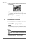
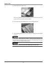
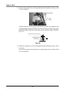
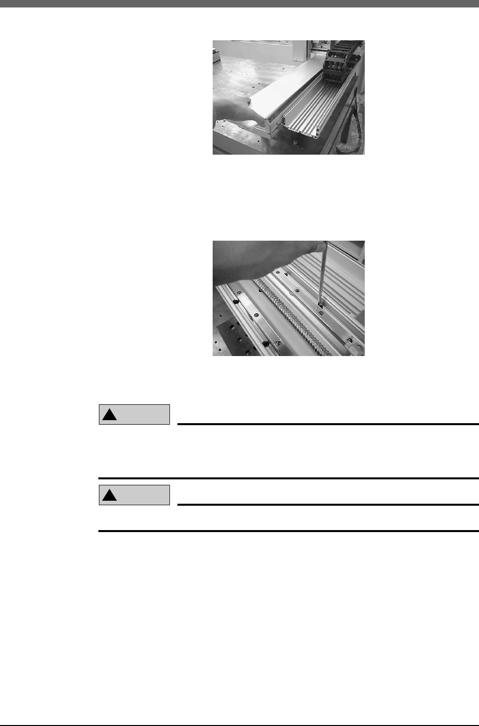
3) Remove the X-axis stroke cover.
If the cover is difficult to remove, manually move the Y-axis to the motor side
stroke end. The cover will be easier to remove.
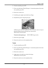
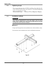
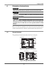
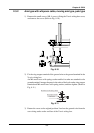
4) Fix the robot onto the installation base with the designated bolts.
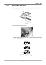
5) After installing, return the stroke cover and X-axis wiring box to the original
positions.
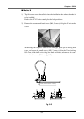
!
CAUTION
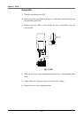
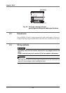
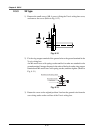
If the X-axis wiring box was slid in step 2), install so that the end face of the
X-axis wiring box and end face of the X-axis are on the same plane. The X-axis
wiring box and frame bracket could interfere.
!
CAUTION
Take care not to catch the wiring when assembling the stroke cover.