


9-16
Chapter 9 MXYX
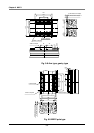
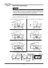
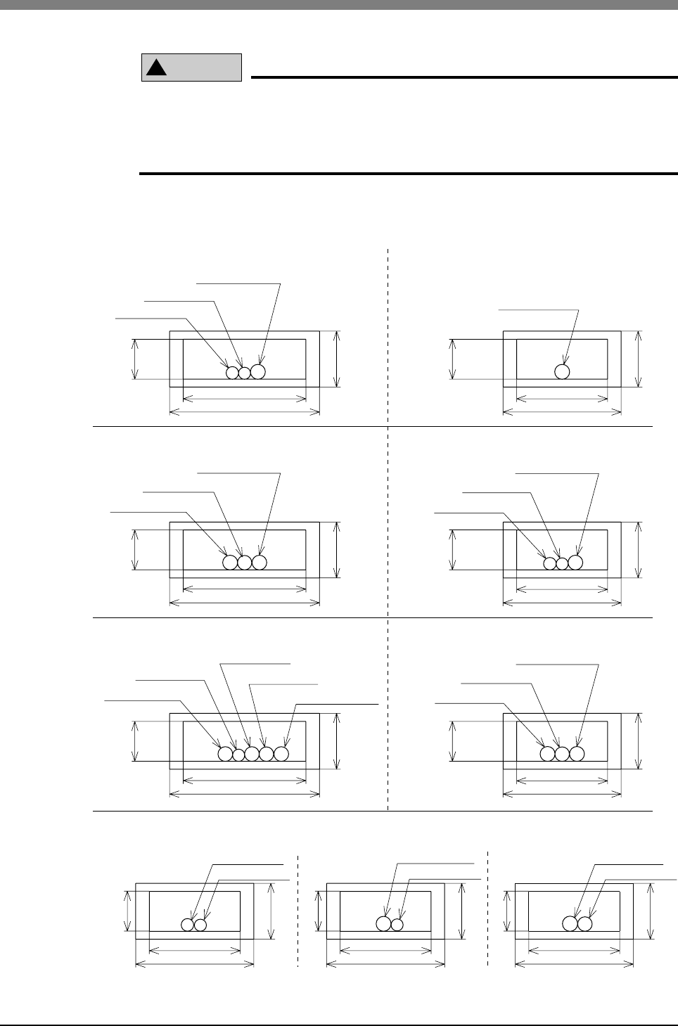
4-1-2 Cable carrier specifications
!
CAUTION
When setting the harness and air tube into the cable carrier, make sure that the
total cross-sectional area of all wires and pipes, including the YAMAHA cable,
inside the cable carrier does not exceed 30% of the cable carrier’s cross-sec-
tional area. (This ratio is called the cable carrier space factor.)
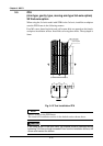
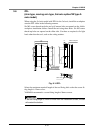
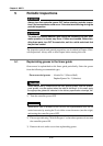
The cross-sectional shape of the cable carrier, and the shape of the cable mounted
initially by YAMAHA are shown below.
Fig. 9-15
User I/O wire φ10.1
User I/O wire φ10.1
Power wire φ7.6
Signal wire φ8.2
User I/O wire φ10.1
User I/O wire φ10.1
Power wire φ9.8
Power wire φ9.8
Power wire φ7.6
Signal wire φ10.1
Signal wire φ11
Signal wire φ10.1
User I/O wire φ10.1
Power wire φ7.6
Signal wire φ8.2
User I/O wire φ10.1
Power wire φ9.8
Signal wire φ 11
25
77
93
57
73
57
73
57
73
93
25
77
93
77
25
25
2525
35
353535
3535
Power wire φ9.8
Signal wire φ11
Power wire φ7.6
Signal wire φ8.2
57
73
25
35
57
73
25
35
57
73
25
35
2-axis specifications X-Y cable carrier
3-axis specifications X-Y cable carrier
4-axis specifications X-Y cable carrier
2-axis I/O specifications Y-axis cable carrier
3-axis specifications Y-Z cable carrier
4-axis specifications Y-Z cable carrier
XZ type 3-axis specifications Z-R cable carrier
4-axis specifications Z-R cable carrier
(ZRFL)
(ZFH)
(ZRFH)
Power wire φ7.6
Signal wire φ10.1