


10-6
Chapter 10 HXYX
1-3 Installation method 3 (Gantry type support axis)
Install the gantry type support axis in the following manner.
!
CAUTION
Move the X-axis as much as possible, and tighten the bolts where the move-
ment is the lightest.
Set the X-axis and guide rail parallelism during installation. Make sure that
there is no difference in the height direction of the X-axis and guide rail installa-
tion surface.
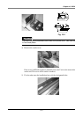
1) Fix the robot onto the specified position of the installation base with bolts.
Do not tighten the guide rail bolt at this time. Securely fix the X-axis section
onto the installation base.
2) When the ZR-axis is provided, or if tools are already attached, move as
close to the X-axis side as possible so that a load is not applied on the
guide rail.
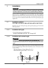
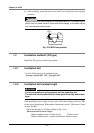
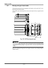
3) Loosen the bolt for the Y-axis and support installation bracket. (Refer to
following drawing.)
4) Temporarily fix the guide rail onto the installation base with bolts.
The parallelism of the guide rail and X-axis must be set using a dial gauge or
pick gauge, etc.
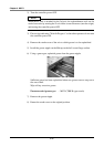
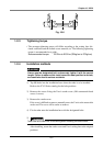
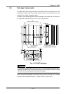
5) To easily set the parallelism, first tighten the bolt loosened in step 3).
Set the X-axis near one end, and tighten the bolt on the guide rail end in this
state. Next, move the X-axis to the opposite end, and tighten the bolt on the
opposite side of the guide rail in this state. Repeat this until all bolts have
been tightened.
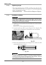
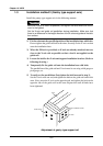
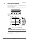
Adjustment of gantry type support rail
Y-axis
Guide rail stay
Bolts
Support installation bracket