


8-22
Chapter 8 SXYX
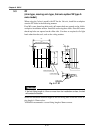
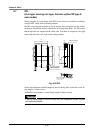
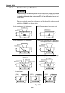
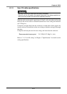
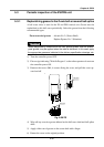
4-1-2 Cable carrier specifications
!
CAUTION
When setting the harness and air tube into the cable carrier, make sure that the
total cross-sectional area of all wires and pipes, including the YAMAHA cable,
inside the cable carrier does not exceed 30% of the cable carrier’s cross-sec-
tional area.
The cross-sectional shape of the cable carrier, and the shape of the cable mounted
initially by YAMAHA are shown below.
Fig. 8-23
User I/O wire φ10.1
User I/O wire φ10.1
Power wireφ7.6
Signal wire φ8.2
User I/O wire φ10.1
User I/O wire φ10.1
Power wire φ9.8
Power wire φ9.8
Power wire φ7.6
Signal wire φ10.1
Signal wire φ11
Power wire φ9.8
Signal wire φ10.1
User I/O wire φ10.1
Power wire φ7.6
Signal wire φ8.2
User I/O wire φ11
Power wire φ9.8
Signal wire φ11
25
77
93
57
73
57
73
57
73
93
25
77
93
77
25
25
2525
35
3535
57
73
25
35
57
73
25
35
57
73
25
35
35
3535
Signal wire φ11
Power wire φ7.6
Signal wire φ10.1
Signal wire φ8.2
Power wire φ7.6
2-axis specifications X-Y cable carrier
3-axis specifications X-Y cable carrier
4-axis specifications X-Y cable carrier
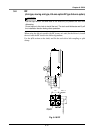
2-axis I/O specifications Y-axis cable carrier
XZ type 2-axis specifications X-Z cable carrier
3-axis specifications Y-Z cable carrier
XZ type 3-axis specifications X-Z cable carrier
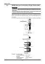
4-axis specifications Y-Z cable carrier
4-axis specifications
(ZRFL) (ZRFH)
Z-R cable carrier
(ZFH)