


9-17
Chapter 9 MXYX
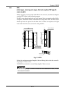
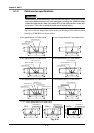
4-1-3 User I/O cable specifications
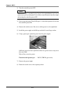
!
CAUTION
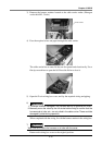
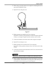
Securely crimp the pin and insert into the pin connector.
Failure to do so will prevent the signals and power from being supplied cor-
rectly, and may prevent the device from operating correctly.
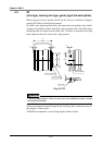
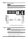
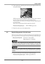
With the cable carrier model, signal wires (0.3mm
2
× 10 wires) that can be used
freely by the user are laid as a standard between the X-axis wiring box and final
axis' wiring box.
Connectors and pins fitted onto the connectors on both ends of this signal wire
are also enclosed. Attach these to the user wiring to eliminate wiring led through
the robot.
Crimp the enclosed pins onto the user wiring, and insert into the connector.
Recommended crimping tool YC-122R (J.S.T. Mfg Co., Ltd.)
Refer to "1-2. User I/O wiring" in Chapter 5 "Specifications" for details on the
wiring specifications.