


11-17
Chapter 11 FXYBX/SXYBX
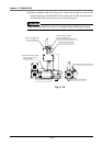
4-2-1 Examples of wiring and piping with Whipover cable
!
CAUTION
Securely crimp the pin and insert into the pin connector.
Failure to do so will prevent the signals and power from being supplied cor-
rectly, and may prevent the device from operating correctly.
1) Crimp the user's cable and tool wiring onto the enclosed connector.
Refer to section “1-2. User I/O cable” in Chapter 5 “Specifications” for de-
tails on the enclosed connector and pin specifications.
2) When using an air tube, prepare an air coupler for connecting the user air
tube with the YAMAHA air tube.
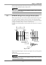
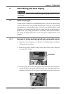
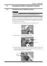
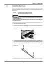
3) Remove the resin cover from the end face of the X-axis wiring box. (M4
screw, 4 screws)
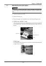
4) Rubber grommets are attached to the X-axis wiring box.
Open holes (or notches) in these grommets, and pass the required cables and
air tubes, etc., through. Crimp the enclosed connectors onto the cable before-
hand.
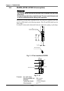
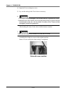
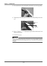
5) Pull the I/O connector and air tube out of the X-axis wiring box. In the same
manner, pull the user cable and air tube passed in step 4) out from the wiring
box.
!
CAUTION
Carefully pull out the minimum length of wiring and air tube with which connec-
tions can be made.
If these are pulled with force, trouble such as dislocation or pin faults could
occur.
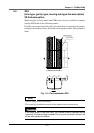
6) Connect the connectors, and connect the air tubes using the air couplers.
Return the air tube into the wiring box after connecting.
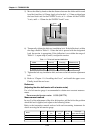
7) Open the Y-axis wiring box cover. (M4 screw, 4 screws)
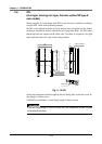
8) Set the required cables and air tubes, etc., into the Y-axis wiring box.
Crimp the enclosed connectors onto the cable beforehand.
9) Connect the connector in the same manner as the X-axis, and connect the air
tube using an air coupler, etc.
If wires are led out from the Y-axis wiring box, use the rubber grommet at-
tached to the upper cover of the Y-axis wiring box.