


11-24
Chapter 11 FXYBX/SXYBX
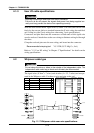
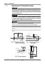
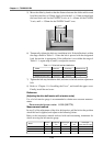
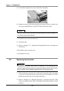
5) Move the slider by hand so that the distance between the slider end face and
base block end face is 150mm. Apply a load at the L = 115mm position from
the base block end for the FXYBX X-axis, at L = 65mm for the FXYBX
Y-axis, and L = 129mm for the SXYBX X and Y axes.
150mm
L
150mm
L
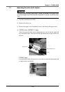
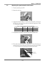
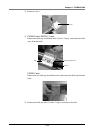
6) Temporarily tighten the belt stay installation bolt. If the deflection is within
the range shown in Table 11-1 when the belt is pressed with the designated
load, the tension is appropriate. If the deflection is not within the range of
Table 11-1, repeat steps 4) and 5) to adjust the tension.
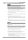
Model Load (N)
Load (kgf)
Deflection(mm)
FXYBX X-axis
FXYBX Y-axis
SXYBX X-axis, Y-axis
4.9 to 5.9
5.9 to 6.9
5.9 to 6.9
0.5 to 0.6
0.6 to 0.7
0.6 to 0.7
2
2
2
Table 11-1 Drive belt load and deflection
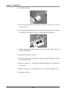
7) Tighten the belt stay installation bolt, and remove the belt tension adjustment
bolt.
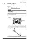
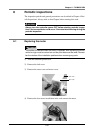
8) Refer to “Chapter 11 6. Installing the Cover”, and install the upper cover.
Finally, install the end cover.
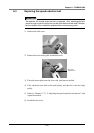
Reference
(Adjusting the drive belt tension with a tension meter)
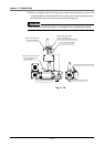
Use of a belt tension gauge is recommended to obtain more accurate measure-
ments.
Recommended tension meter U-505 (UNITTA)
Measurement method
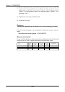
In step 5) of the adjustment of the drive belt tension, pull the belt at the position
where the load is applied, and adjust to the following values.
Refer to the instruction manual enclosed with each measuring instrument for
details on using the belt tension gauge.
Model
Tension
(N)
Frequency
(Hz)
Span length
(mm)
Belt width
(mm)
FXYBX X-axis
FXYBX Y-axis
SXYBX X-axis, Y-axis
127 to 147
127 to 147
169 to 188
86 to 93
117 to 126
79 to 84
230
170
258
Unit weight
(g/mm width×m length)
4.0
4.0
4.0
20
20
25