


5-1
Chapter 5 Specifications
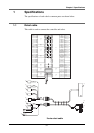
1 Specifications
The specifications of each robot's common parts are shown below.
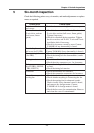
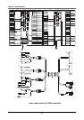
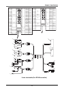
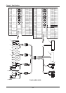
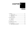
1-1 Robot cable
This cable is used to connect the controller and robot.
2-axis robot cable
0.3sq
twisted pair
Gray/White
2
34
32
1
1
4
Ring-tongue terminal
!1
4
FG
GND24
ORG
24V
GND24
HLIM
GND24
HLIM
31
Green
Green
27
30
29
10
11
28
16
YM
e
XM
w
0.3sq
twisted pair
0.3sq
twisted pair
0.3sq
twisted pair
0.3sq
twisted pair
0.3sq
twisted pair
0.3sq
twisted pair
0.3sq
twisted pair
4
Brake
U
Green
Green
Purple
Black
Red
Gray
Brown
Green
Orange
Blue
Yellow
Yellow/Black
Green/White
Orange/White
Pink/Black
Pink
Brown/White
Blue/Red
Red/White
White
0.75sq
0.75sq
0.75sq
0.75sq
0.75sq
0.75sq
0.75sq
0.3sq
0.3sq
twisted pair
0.3sq
YP
y
0.3sq
XP
r
XY
q
Yellow /Green
YM
!0
XM
o
ORG
i
Resolver
W
V
U2
3
XBK
t
R1
R2
DG
S2
S4
S1
S3
MB-
MB+
S3
24
23
22
21
20
19
66
5
5
7
4
3
2
1
4
3
2
1
R1
DG
S2
7
14
7
5
6
Signal
2
1
2
1
1
3
2
3
2
1
6
5
4
3
2
3
2
1
3
2
1
4
FG
4
3
ConnectionConnector
No
WireColor/No.Connector
No
25
S4
Resolver
S1
R2
Ring-tongue terminal
W
V
Brake
Sensor
YBK
u
MB-
MB+
XBK
XM
XP
YBK
YP
YM
XY
YM
XM
o
!1
!0
r
t
y
u
ORG
i
q
w
e