


12-5
Chapter 12 HXYLX
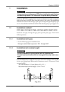
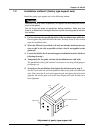
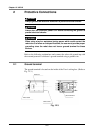
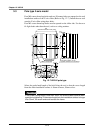
1-2 Installation method 3 (Gantry type support axis)
Install the gantry type support axis in the following manner.
!
CAUTION
Move the X-axis as much as possible, and tighten the bolts where the move-
ment is the lightest.
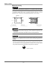
Set the X-axis and guide rail parallelism during installation. Make sure that
there is no difference in the height direction of the X-axis and guide rail installa-
tion surface.
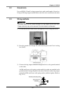
1) Fix the robot onto the specified position of the installation base with bolts.
Do not tighten the guide rail bolt at this time. Securely fix the X-axis section
onto the installation base.
2) When the ZR-axis is provided, or if tools are already attached, move as
close to the X-axis side as possible so that a load is not applied on the
guide rail.
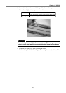
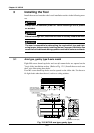
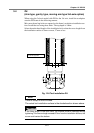
3) Loosen the bolt for the Y-axis and support installation bracket. (Refer to
following drawing.)
4) Temporarily fix the guide rail onto the installation base with bolts.
The parallelism of the guide rail and X-axis must be set using a dial gauge or
pick gauge, etc.
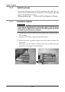
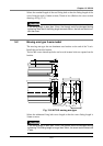
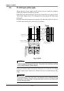
5) To easily set the parallelism, first tighten the bolt loosened in step 3).
Set the X-axis near one end, and tighten the bolt on the guide rail end in this
state. Next, move the X-axis to the opposite end, and tighten the bolt on the
opposite side of the guide rail in this state. Repeat this until all bolts have
been tightened.
Y- a x i s
Guide rail stay
Bolts
Support installation bracket
Adjustment of gantry type support rail