


11-28
Chapter 11 FXYBX/SXYBX
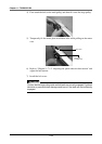
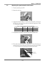
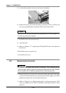
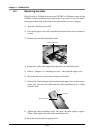
5) Loosen the two pulley set screws, and remove the pulley.
6) Replace the motor, and attach the pulley to the motor. Insert so that the two
set screws perpendicularly contact the D face of the motor shaft.
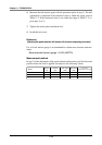
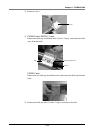
NOTE
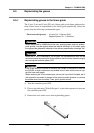
The parts can be correctly assembled by projecting the set screws by approx. 0.1
to 0.2mm from the inner diameter.
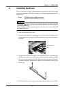
7) Install the motor onto the main body.
8) Attach the belt.
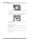
9) Refer to “Chapter 11 7. Adjusting the Timing Belt Tension” and adjust the
belt tension.
10) Install the motor case and cover.
11) Install the belt cover.
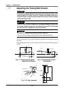
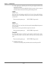
8-2 Replacing the drive belt
!
CAUTION
The position will deviate when the belt is replaced. After replacing the belt,
return-to-origin must be carried out and the point data must be reset. Remem-
ber the relation of the installation positions when removing any parts.
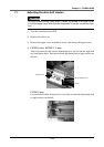
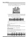
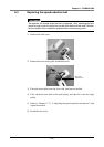
1) Remove the end cover from the counter-motor end, and remove the upper
cover. (On robot models having a long stroke, pull off the upper cover with a
parallel movement in the axis movement direction.)
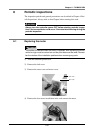
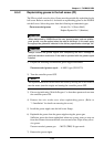
2) Refer to “Chapter 11 8-1. Replacing the motor”, and remove the motor. (This
step is not required if the motor is installed at horizontal position or lower
position.)