


10-23
Chapter 10 HXYX
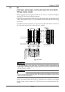
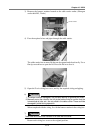
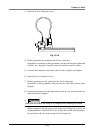
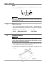
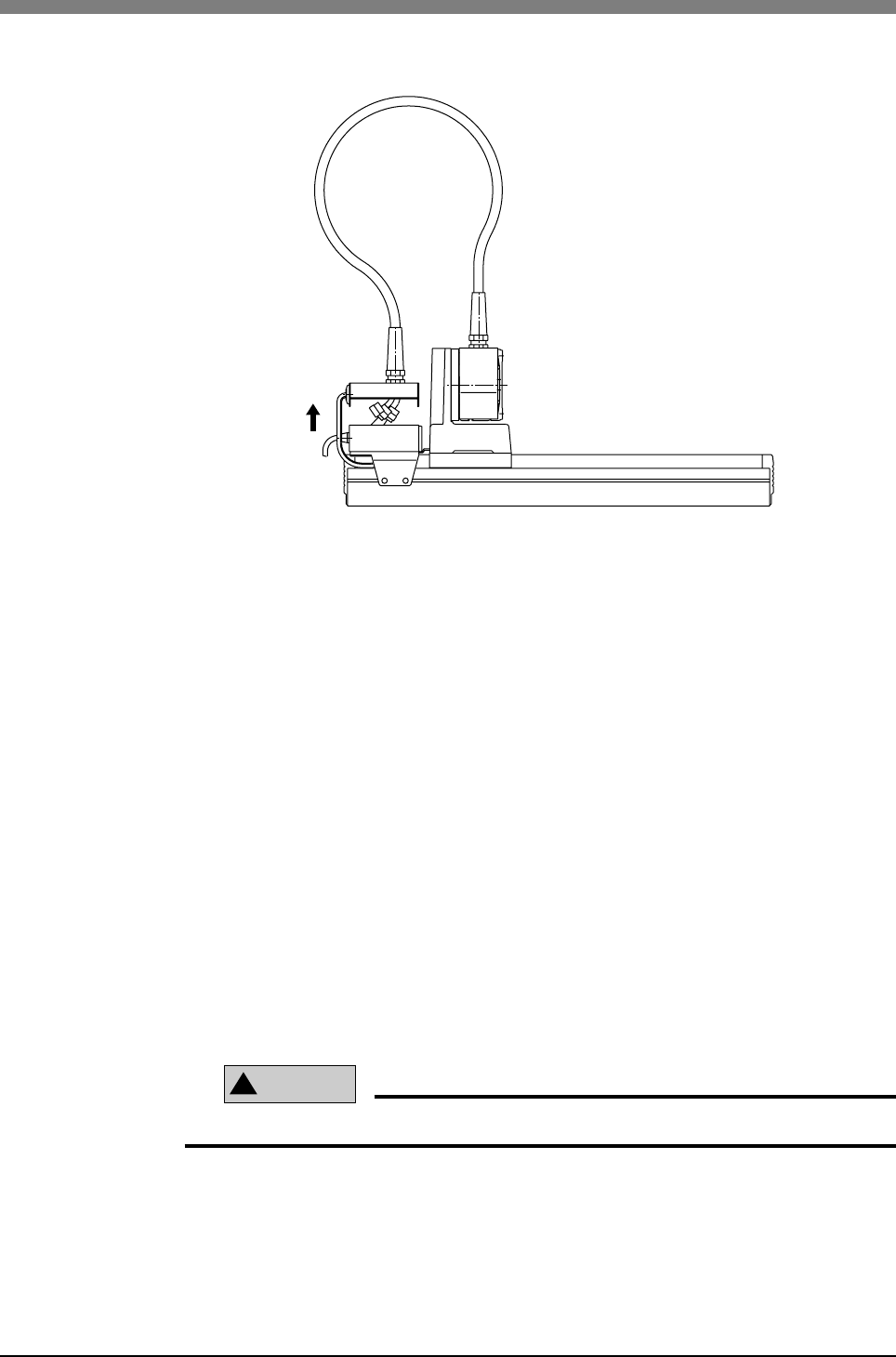
3) Open the X-axis wiring box cover.
Fig. 10-19
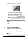
4) Rubber grommets are attached to the X-axis wiring box.
Open holes (or notches) in these grommets, and pass the required cables and
air tubes, etc., through. Crimp the enclosed connectors onto the cables.
5) Connect the connectors, and connect the air tubes using the air couplers.
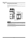
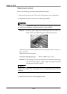
6) Open the Y-axis wiring box cover.
7) Rubber grommets are also attached to the Y-axis wiring box.
Open holes in these grommets, and pass the tool side cables and air tubes
through.
8) Connect the connectors in the same manner as the X-axis, and connect the air
tubes with the air couplers.
9)
!
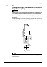
CAUTION
Take care not to catch the wiring or air couplers when installing the covers.
When completed with all wiring work, return each wiring box cover to the
original positions. Sandwich the X-axis wiring and air tube with the protec-
tive material at the wire lead-out port of each wiring box.