


DCS-100 • User’s Guide 19
NK==fåíêçÇìÅíáçå
Connectivity Diagram
`çååÉÅíáîáíó=aá~Öê~ã
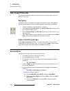
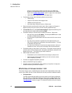
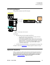
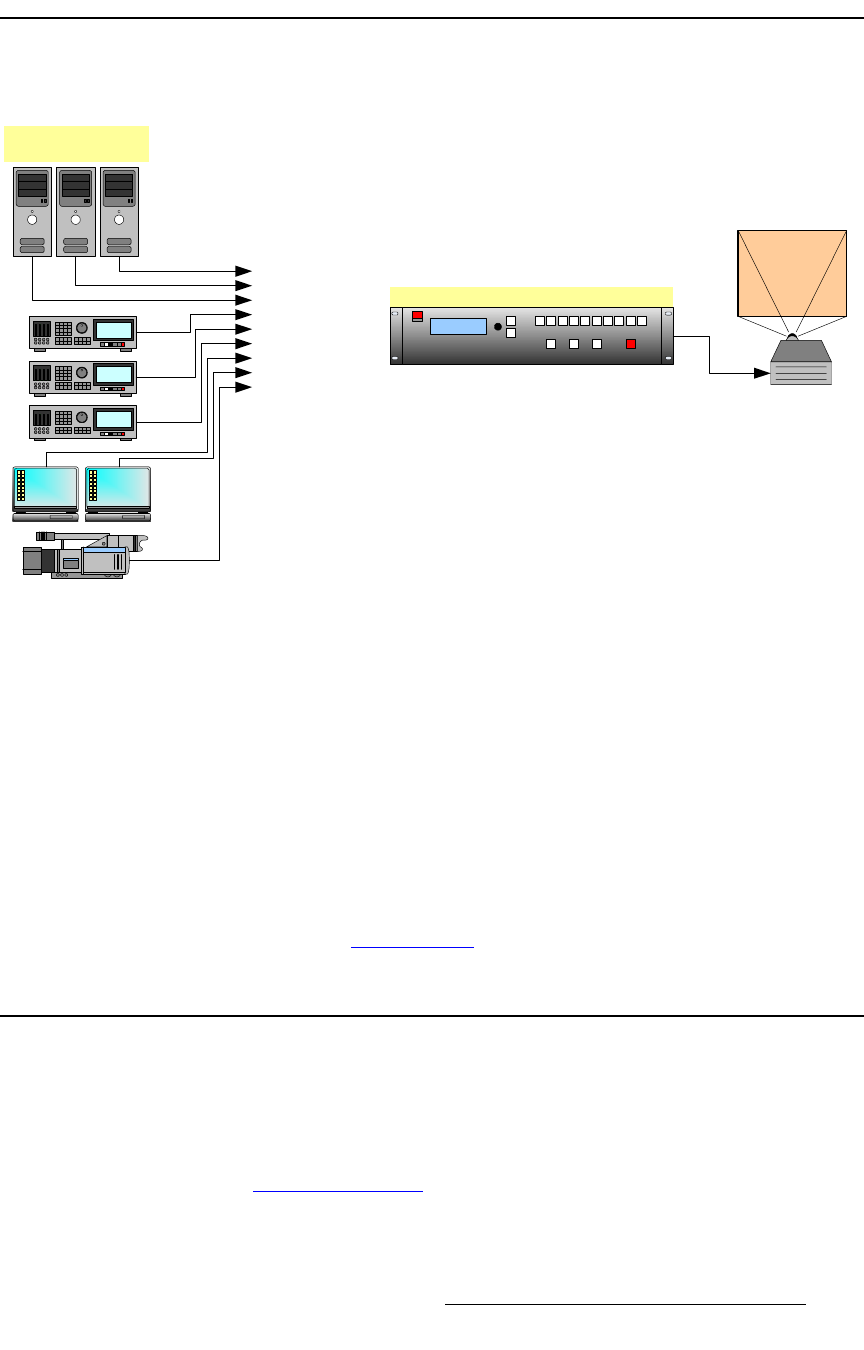
The figure below illustrates a basic DCS-100 system.
Figure 1-1. Block diagram, DCS-100 system
In the diagram:
• Up to nine sources can be connected to the DCS-100:
~ 6 x analog inputs (on HD-15 connectors), for a variety of YUV and
RGBHV sources, including CVBS and Y/C.
~ 2 x DVI inputs, for computer sources. These two DVI connectors also
support analog RGB inputs, and these inputs are universal, and accept
all types of sources — just like the six HD-15 connectors. (To connect
analog sources, use a customer-supplied DVI to HD-15 adapter.)
~ 1 x SD-SDI or HD-SDI input.
• The DCS-100 connects to the projector (or other target device) via analog or DVI.
In Chapter 2, refer to the “Inputs Section
” heading on page 24 for details on all inputs.
^ééäáÅ~íáçå=nìÉëíáçåë
At Barco, we take pride in offering unique solutions to demanding technical problems. If
you have application questions, require further information or would like to discuss your
application requirements in more detail, please call (866) 469-8036. Our Customer
Support Engineers will be happy to supply you with the support you need. Refer to
Appendix C, “Contact Information
” on page 155 for details.
DCS-100
Inputs 1 - 6 (Analog)
Inputs 7 - 8 (DVI)
Input 9 (HD/SD SDI)
Sample Source Input
Devices