


DCS-100 • User’s Guide 27
2. Hardware Orientation
DCS-100 Rear Panel
a`pJNMM=oÉ~ê=m~åÉä
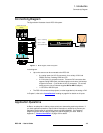
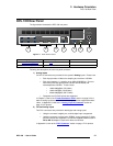
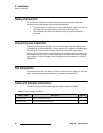
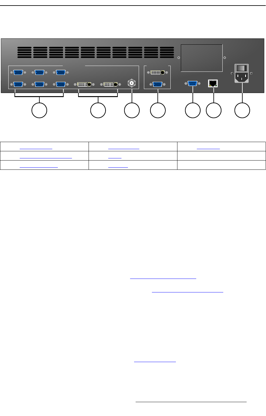
The figure below illustrates the DCS-100 rear panel:
Figure 2-1. DCS-100 Rear Panel
Following are descriptions of each rear panel connector:
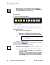
1) Analog Inputs
Six HD-15 connectors are provided for the system’s Analog inputs. Please note:
~ Each input provides 10-bits/color sampling at a maximum 165 MHz.
~ Each input supports 1:1 sampling up to 1600x1200@60 Hz. Sources
with native pixel rates greater than 165 MHz will be filtered and
undersampled at 165 Mhz. These include:
• 1920x1080p@60 (173.0 MHz)
• 1920x1200@60 (193.25 MHz)
• 2048x1080p@60 (183.75 MHz)
~ Composite and S-Video formats are supported.
In Chapter 3, refer to the “Format Connection Table” section on page 34 for a
table of analog inputs that you can connect using a customer-supplied breakout
cable. In Appendix A, refer to the “Analog 15-pin D Connector
” section on
page 116 for pinouts.
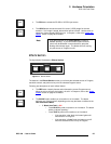
2) DVI and Analog Inputs
Two DVI-I connectors are provided for both digital and analog inputs.
~ Using the connector’s digital pins, an 8-bit digital input is supported.
~ Using the connector’s analog pins, RGBHV, analog composite, S-Video,
and YUV formats are supported. A customer-supplied breakout cable or
DVI to HD-15 adapter is required for these connections.
In Appendix A, refer to the “DVI-I Connector” section on page 117 for pinouts.
100 - 240 VAC
50 – 60 Hz, 1.9A
ETHERNET
Model
DCS-100
SERIAL
Input 1
Input 2
Input 3
Input 4
Input 5
Input 6 Input 7 Input 8
HD/SD SDI
VIDEO INPUTS MAIN OUTPUTS
3 71 2 4 5 6
1) Analog Inputs 4) Main Outputs 7) AC Power
2) DVI and Analog Inputs 5) Serial
3) HD/SD SDI Input 6) Ethernet