


28 DCS-100 • User’s Guide
2. Hardware Orientation
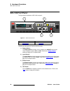
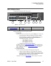
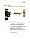
DCS-100 Rear Panel
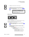
3) HD/SD SDI Input
One BNC connector is provided for the SD-SDI or HD-SDI input.
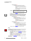
4) Main Outputs
Two connectors are provided for the DCS-100’s main program outputs. Both
outputs have the same resolution, and both can be used simultaneously.
~ One DVI-I connector is provided for the system’s digital program output.
There are no analog outputs on this connector. In Appendix A, refer to
the “DVI-I Connector
” section on page 117 for pinouts.
~ One HD-15 connector is provided for the system’s analog output. In
Appendix A, refer to the “Analog 15-pin D Connector” section on
page 116 for pinouts
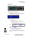
5) Serial
One DB-9 connector is provided for Serial communications with the DCS-100
system. The port is also used for diagnostics or command-line operations.
6) Ethernet
One RJ-45 connector is provided for 10/100BaseT Ethernet communications with
the DCS-100 system. The port is used for running the built-in web-based GUI, for
diagnostics, or for command-line operations via Telnet (using port 23).
S telnet 192.168.0.10 23
In Appendix A, refer to the “Ethernet Connector
” section on page 118 for
pinouts.
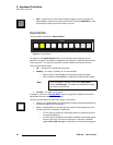
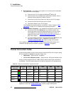
7) AC Power
One AC Connector is provided for connecting DCS-100 to AC. The integral
switch turns the chassis on and off. In Appendix A, refer to the “Physical and
Electrical Specifications” section on page 115 for power details.
Note
The DVI-I connector allows you to use both DVI-D and DVI-I
cables as required.