34 DCS-100 • User’s Guide
3. Installation
Format Connection Table
3. GUI connection — to configure your system to run from the built-in web-based
GUI, perform the following steps:
a. Ensure that your PC (or laptop) uses Windows
®
2000 or XP.
b. Ensure that your PC (or laptop) has a web browser installed, such as
Windows Internet Explorer
®
or Mozilla Firefox
®
.
c. Ensure that you have Java Version 6 or later on your PC (or laptop).
d. Connect the DCS-100’s Ethernet port to a Switch.
e. Connect the Switch to your PC (or laptop).
This completes the required “physical” connections. Refer to Chapter 5, “GUI
Operations” on page 101 for installation and operating instructions.
4. Communications connection — two methods are available for remote control:
a. Connect the DCS-100’s Ethernet port to an Ethernet switch, and
connect the switch to the other Ethernet devices in your local system.
This enables you to communicate with the DCS-100 via Telnet. In
Appendix B, refer to the “Communicating with DCS-100” section on
page 125 for details.
b. For a serial remote connection, connect the DCS-100’s Serial port to the
serial port of a laptop or a PC. In Appendix B, refer to the
“Communicating with DCS-100
” section on page 125 for details
This completes system signal installation. Please continue with system setup, menu
orientation and operations, as outlined in Chapter 4, “Operation” on page 35.
cçêã~í=`çååÉÅíáçå=q~ÄäÉ
Use the following table to connect various source formats to the DCS-100, using the analog
HD-15 connectors (on Inputs 1 through 6). Please note:
• RGB format — typical devices: Computers
• YUV or YP
b
P
r
(Betacam) format — typical devices: DVD player, Betacam deck
Using a customer supplied VGA to 5 x BNC breakout cable, multiple input combinations
are possible. Cells with checks denote the connections required for the indicated format.
Please contact Barco Technical Support for information on obtaining breakout cables. In
Appendix C, refer to the “Contact Information
” section on page 156 for details.
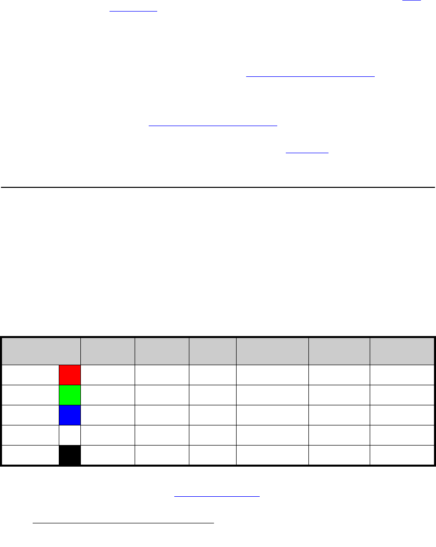
Table 3-2. Analog Input Combinations using Breakout Cable
Breakout Cable
Wire Color
Composite
Video
S-Video
(Y/C)
YUV
(YP
b
P
r
)
RGB
Sync on Green
RGB
Comp Sync
RGB
Separate H V
R
3 (P
r
) 3
33
G
33 (Lum)
3 (Lum)
333
B
3 (Chrom)
3 (P
b
)
333
H Sync
33
V Sync
3


