


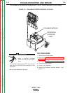

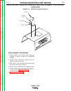

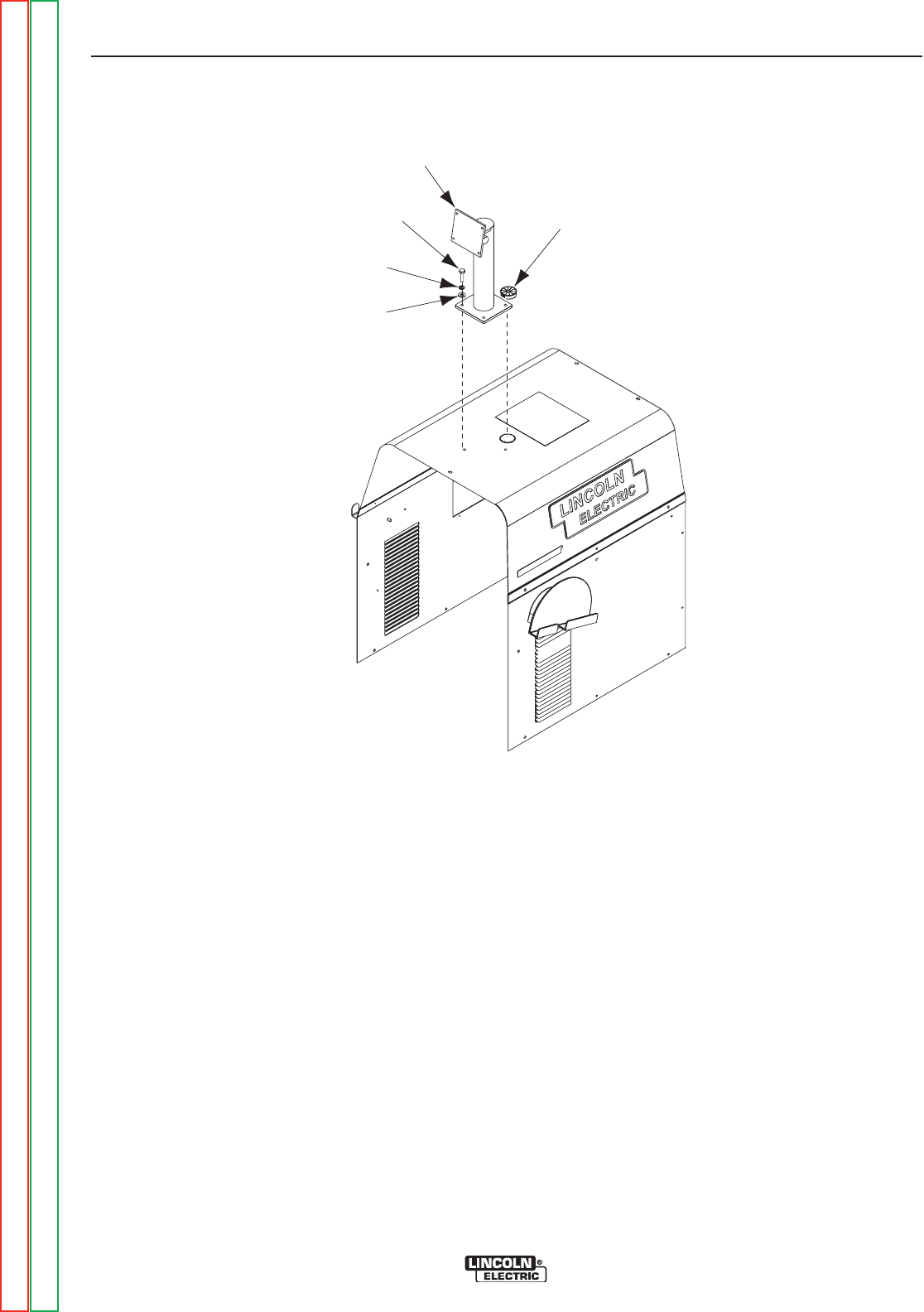
Mounting
S
crews (4)
Lock Washer
W
asher
P
edestal
Grommet
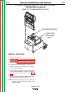
FIGURE F.15 – CASE COVERS
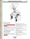
CASE COVER REMOVAL AND REPLACEMENT PROCEDURE (continued)
REMOVAL PROCEDURE
1. Remove input power.
2. Perform the Monitor and Pedestal Removal
Procedure.
3. Using 3/8” wrench, remove the nine screws
securing the case roof.
4. Remove the black plastic grommet securing the
VGA and monitor input cable to the roof. See
Figure F.15.
5. Carefully remove roof from unit while negotiating
wires and cables through the hole in the roof
where grommet was removed.
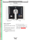
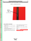
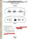
COUPON DRAWER REMOVAL
1. Open drawer completely.
2. Push drawer-release tabs located underneath
slides. Both tabs must be depressed. See
Figure F.16.
3. Pull drawer out and away from machine.
4. Using a 3/8” wrench, remove the seven screws
securing the coupon drawer mounting frame to
the case sides and back.
5. Carefully remove coupon drawer frame from
unit.
RIGHT CASE SIDE REMOVAL
1. Carefully remove the VR GMAW/FCAW device
from the holder.
2. Using a 3/8” wrench, remove the six screws
securing the right case side.
LEFT CASE SIDE REMOVAL
1. Carefully remove the VR SMAW device from the
holder.
2. Using a 3/8” wrench, remove the six screws
securing the left case side.
TROUBLESHOOTING AND REPAIR
F-44 F-44
VRTEX
TM
360
Return to Section TOC Return to Section TOC Return to Section TOC Return to Section TOC
Return to Master TOC Return to Master TOC Return to Master TOC Return to Master TOC