


INSTALLATION
A-8 A-8
VRTEX
TM
360
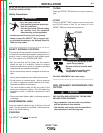
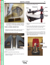
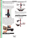
9. Carefully slide swing-arm onto post with the letters
(on the collar) “ABC” up and the grey cable located
on the bottom of the swing arm assembly.
10. Insert a third collar pin at a convenient height for
holding the helmet.
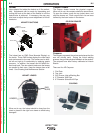
MONITOR:
1. Remove monitor from cardboard box.
2. Remove the cable ties from monitor cables secured
to the monitor mounting post.
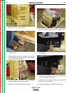
3. Using a Phillips-head screwdriver, carefully mount
the monitor onto the mounting post bracket. Tighten
the four Phillips-head screws securely.
4. Install input power cable and VGA cable into the
monitor.
ADDITIONAL FEATURES:
1. The welding coupons are stored in the coupon
drawer in the rear of the machine.
2. The weld simulation can be displayed on an exter-
nal monitor or projector by using the SVGA output
on the back of the machine. The external display
must support 1024x780 resolution.
3. External speakers may be connected using the
audio jack located on the back of the machine.
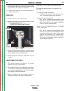
TRACKING SYSTEM FUNDAMENTALS:
The magnetic tracking system is composed of the
following:
• Control Unit (Inside VR Machine)
o Contains the hardware and software neces-
sary to compute position and orientation.
• Source (part of the Swing Arm)
o The source contains electromagnetic coils
enclosed in a plastic shell that emit a magnetic
field. The source is the systemʼs reference
frame for sensor measurements.
• Sensor (in the VR GMAW/FCAW gun, VR SMAW
device, and helmet)
o The sensor contains electromagnetic coils
enclosed in a plastic shell that detect the mag-
netic fields emitted by the source. The sensorʼs
position and orientation are precisely mea-
sured as it moves in reference to the source.
The sensor is completely passive, having no
active voltage applied to it.
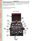
MONITOR (Mounting Screws)
Screws
Input
Power
VGA
Return to Section TOC Return to Section TOC Return to Section TOC Return to Section TOC
Return to Master TOC Return to Master TOC Return to Master TOC Return to Master TOC