


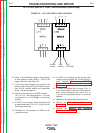


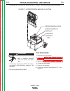

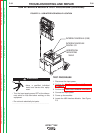
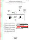

INTERFACE MODULE
DIGITAL I/O
HORIZONTAL
MOUNTING
SHELF
INTERFACE MODULE (USB)
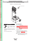
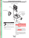
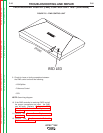
FIGURE F.7 – INTERFACE DIGITAL MODULE I/O LOCATION
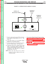
INTERFACE DIGITAL MODULE I/O TEST PROCEDURE (continued)
TROUBLESHOOTING AND REPAIR
F-28 F-28
VRTEX
TM
360
TEST PROCEDURE
1. Disconnect the input power.
2. Perform the Monitor and Pedestal Removal
Procedure.
3. Perform the Case Cover Removal Procedure.
4. Connect the input power.
5. Power up the machine.
6. Locate the Interface Digital Module I/O. See
Figure F.7.
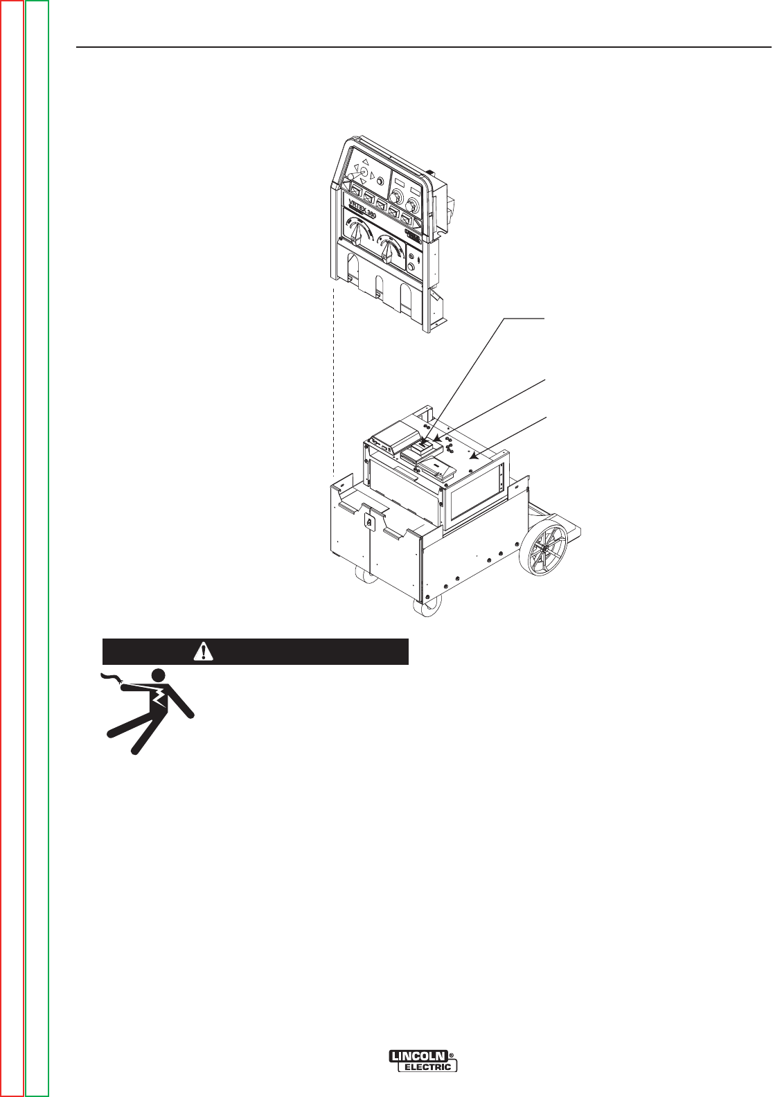
ELECTRIC SHOCK can kill.
• Have a qualified individual
install and service this equip-
ment.
• Turn the input supply power OFF at the discon-
nect switch or fuse box before working on this
equipment.
• Do not touch electrically hot parts.
------------------------------------------------------------------
WARNING
Return to Section TOC Return to Section TOC Return to Section TOC Return to Section TOC
Return to Master TOC Return to Master TOC Return to Master TOC Return to Master TOC