


If for any reason you do not understand the test procedures or are unable to perform the tests/repairs safely,
contact the Lincoln Electric Service Department for technical troubleshooting assistance before you proceed.
Call 1-
888-935-3878
.
CAUTION
TROUBLESHOOTING AND REPAIR
F-6 F-6
VRTEX
TM
360
POWER-UP PROBLEMS
Observe Safety Guidelines detailed in the beginning of this manual.
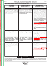
PROBLEMS
(SYMPTOMS)
POSSIBLE AREAS OF
MISADJUSTMENT(S)
RECOMMENDED
COURSE OF ACTION
The VRTEX
TM
360 does not
power up when the ON Switch is
pushed. The green indicator light
does come on and stays on.
The green light indicates that
the CPU Computer Assembly is
receiving input power and
activating the green light via a
USB cable.
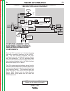
Verify that the green LEDs on
the 5VDC Power Supply and
the 12VDC Power Supply are
on. If they are not, then
perform the 5VDC Power
Supply Test and the 12VDC
Power Supply Test.
Carefully check the input
voltage being applied to the
Monitor at leads #103 to #102.
It should be the same as the
input line voltage. (115-230VAC
single phase). See the wiring
diagram.
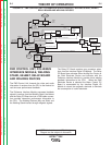
If the above checks are OK
then check for broken cables
and loose connections between
the CPU and the User
Interface, the 12VDC Supply
and the Relay PC Board and
the VGA Splitter, the 5VDC
supply and the FMD Control
Unit, and the Polhemus
Interface Module. See the
wiring diagram.
Return to Section TOC Return to Section TOC Return to Section TOC Return to Section TOC
Return to Master TOC Return to Master TOC Return to Master TOC Return to Master TOC