


INSTALLATION
A-7 A-7
VRTEX
TM
360
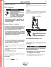
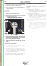
14. Insert the input supply power cord into the back of
the VRTEX
TM
360 and into a standard electrical
outlet capable of 115 to 230 VAC at 4 to 2 Amps.
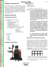
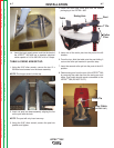
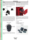
TABLE & SWING ARM SET-UP:
1. Using the 3/16” allen wrench, remove the two ¼” x
20 Allen-head screws from the base assembly.
NOTE: The longer screw is in the top.
2. Insert red post into base assembly aligning the flat
on the pole with the hole.
NOTE: The post will only insert one way.
3. Using the 3/16” allen wrench, secure the post into
position and tighten.
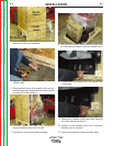
5. Insert one of the collar pins into the post at the #6
location.
6. From the top, slide the table onto the post letting it
rest on the collar pin inserted in previous step.
7. Insert the second collar pin into the post at the #13
position.
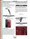
8. Obtain swing-arm from the rear of the VRTEX
TM
360
by removing the cable ties from the swing arm and
cable. Grey cable should remain connected to the
VRTEX
TM
360 (DO NOT CUT!).
Collar
Pins
4. Obtain the three post collar pins from the factory
packaging of the VRTEX
TM
360.
Cable Tie
Swing Arm
Table
Post
T Pin
Grey Cable
(DO NOT CUT)
Return to Section TOC Return to Section TOC Return to Section TOC Return to Section TOC
Return to Master TOC Return to Master TOC Return to Master TOC Return to Master TOC