


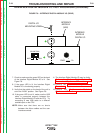

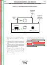

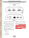

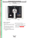


SENSOR 1
SENSOR 2
SOURCE
SYS
RS 232 USB
CONFIG
O
N
ON
OFF
DC
IN
FRONT
BACK
LED
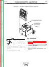
FIGURE F.12 – POLHEMUS INTERFACE MODULE
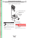
POLHEMUS INTERFACE MODULE TEST PROCEDURE (continued)
7. Check to make sure the LED on the front of the
Polhemus Interface Module is lit. See Figure
F.12.
NOTE: At initial power up, the LED will be red, then
a flashing red. When the machine is com-
pletely initialized, the LED will turn green.
8. Make sure the switch on the back of the
Polhemus Interface Module is in the “ON” posi-
tion.
9. Make sure all the dip switch settings are in the
down position. See Figure F.12.
10. If the LED is lit, check for loose or faulty con-
nections between the FMD control unit and the
following;
• Welding Stand
• CPU
• FMD Control Unit
• Relay PC Board
Note: See wiring diagram.
11. If the LED is not lit, check for the presence of
5VDC at the input terminal. See wiring dia-
gram.
12. If the LED is not lit and the 5VDC is present,
the Polhemus Interface Module may be faulty.
Perform the Polhemus Interface Module
Removal and Replacement Procedure.
12. Perform the Case Cover Replacement
Procedure.
13. Perform the Monitor and Pedestal
Replacement Procedure.
TROUBLESHOOTING AND REPAIR
F-37 F-37
VRTEX
TM
360
Return to Section TOC Return to Section TOC Return to Section TOC Return to Section TOC
Return to Master TOC Return to Master TOC Return to Master TOC Return to Master TOC