


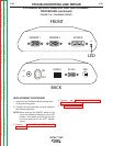
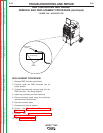


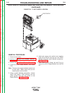
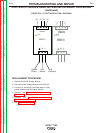
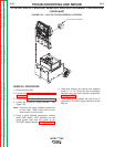
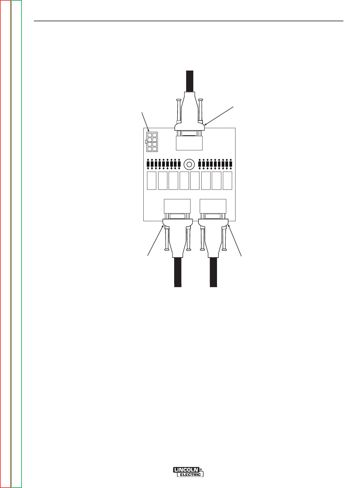
J4
J3
J2
PLUG
J1
FIGURE F.22 – PLUG LOCATION
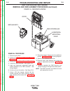
RELAY PC BOARD REMOVAL AND REPLACEMENT PROCEDURE
(continued)
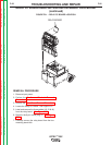
REPLACEMENT PROCEDURE
1. Replace the Relay PC Board.
2. Mount the board to the machine by carefully
pressing the board onto the four mounting
stand-offs.
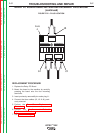
3. Insert previously removed 8-pin molex plug J1.
4. Connect the three cables (J2, J3 & J4) previ-
ously removed.
5. Perform the Case Cover Replacement
Procedure.
6. Perform the Monitor and Pedestal
Replacement Procedure.
7. See Retest After Repair.
TROUBLESHOOTING AND REPAIR
F-57 F-57
VRTEX
TM
360
Return to Section TOC Return to Section TOC Return to Section TOC Return to Section TOC
Return to Master TOC Return to Master TOC Return to Master TOC Return to Master TOC