


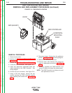

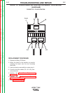


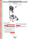
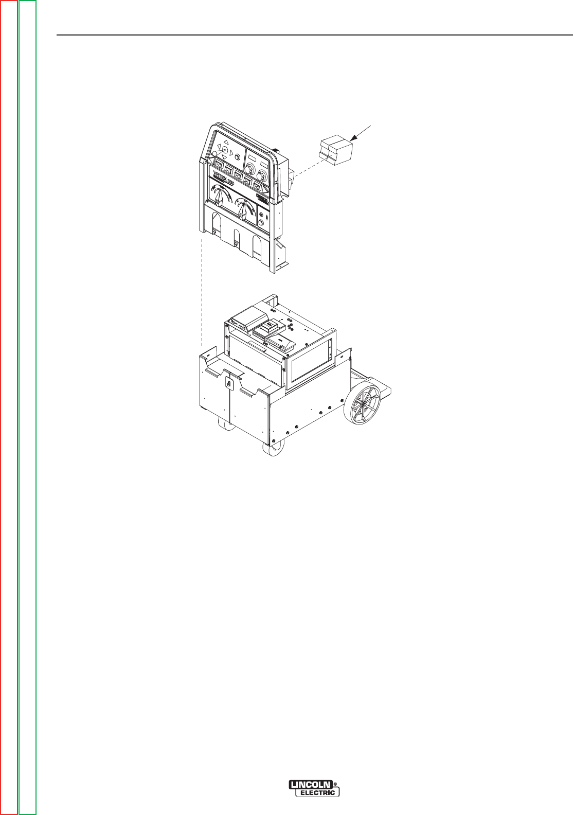
5 VOLT SUPPLY
FIGURE F.23 – 5 VOLT SUPPLY LOCATION
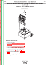
5VDC SUPPLY MODULE REMOVAL AND REPLACEMENT PROCEDURE
(continued)
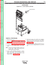
REMOVAL PROCEDURE
1. Remove input power.
2. Perform the Monitor and Pedestal Removal
Procedure.
3. Perform the Case Cover Removal Procedure.
4. Locate the 5VDC Supply Module. See Figure
F.23.
Note: There are two supply modules located next
to each other. Make certain that you are
removing the correct module.
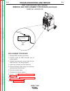
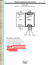
5. Using a small flathead screwdriver, remove
leads 102A (white), 103B (pink/red) and the
green ground lead from the bottom of the
Supply Module. See Figure F.24.
6. Label and remove the positive and negative
leads (81,81,50,50) from the top of the 5VDC
Module using the small flathead screwdriver.
See Figure F.24.
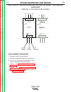
7. Push down on the release tab and lift up to
remove the 5VDC Supply Module from the DIN
rail.
TROUBLESHOOTING AND REPAIR
F-60 F-60
VRTEX
TM
360
Return to Section TOC Return to Section TOC Return to Section TOC Return to Section TOC
Return to Master TOC Return to Master TOC Return to Master TOC Return to Master TOC