


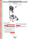
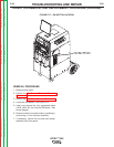

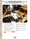
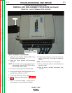
INTERFACE MODULE
DIGITAL I/O
HORIZONTAL
MOUNTING
SHELF
INTERFACE MODULE (USB)
FIGURE F.29 – INTERFACE MODULE DIGITAL I/O LOCATION
INTERFACE MODULE DIGITAL I/O
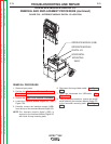
REMOVAL AND REPLACEMENT PROCEDURE (continued)
REMOVAL PROCEDURE
1. Remove input power.
2. Perform the Monitor and Pedestal Removal
Procedure.
3. Perform the Case Cover Removal Procedure.
4. Locate the Interface Module Digital I/O. See
Figure F.29.
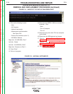
5. Carefully remove the interface module (USB)
from the top of the Interface Module Digital I/O.
NOTE: The interface module digital (USB) is
secured to the Interface Module Digital I/O
with Hook & Loop mounting pads.
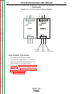
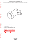
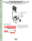
6. Disconnect the large ribbon cable. See Figure
F.30.
7. Label and disconnect the USB cable. See
Figure F.30.
8. Using a phillips screwdriver, remove the single
screw securing the Interface Module Digital I/O
to the horizontal mounting shelf. See Figure
F.30.
TROUBLESHOOTING AND REPAIR
F-72 F-72
VRTEX
TM
360
Return to Section TOC Return to Section TOC Return to Section TOC Return to Section TOC
Return to Master TOC Return to Master TOC Return to Master TOC Return to Master TOC