


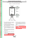

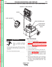

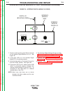

RED LED
F
R
O
N
T
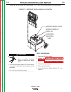
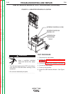
FIGURE F.6 – FMD CONTROL UNIT
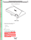
FACE MOUNTED DISPLAY (FMD) CONTROL UNIT TEST (continued)
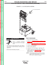
9. Check for loose or faulty connections between
the FMD control unit and the following;
• VGA Splitter
• Polhemus Control
• CPU
NOTE: See wiring diagram.
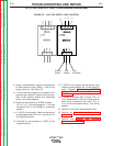
10. If the FMD controller is receiving 5VDC and all
the proper connections are intact, the FMD
may be faulty. Replace. Perform the FMD
Control Unit Removal and Replacement
Procedure.
11. Perform the Case Cover Replacement
Procedure.
12. Perform the Monitor and Pedestal
Replacement Procedure.
TROUBLESHOOTING AND REPAIR
F-25 F-25
VRTEX
TM
360
Return to Section TOC Return to Section TOC Return to Section TOC Return to Section TOC
Return to Master TOC Return to Master TOC Return to Master TOC Return to Master TOC