


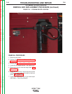

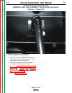


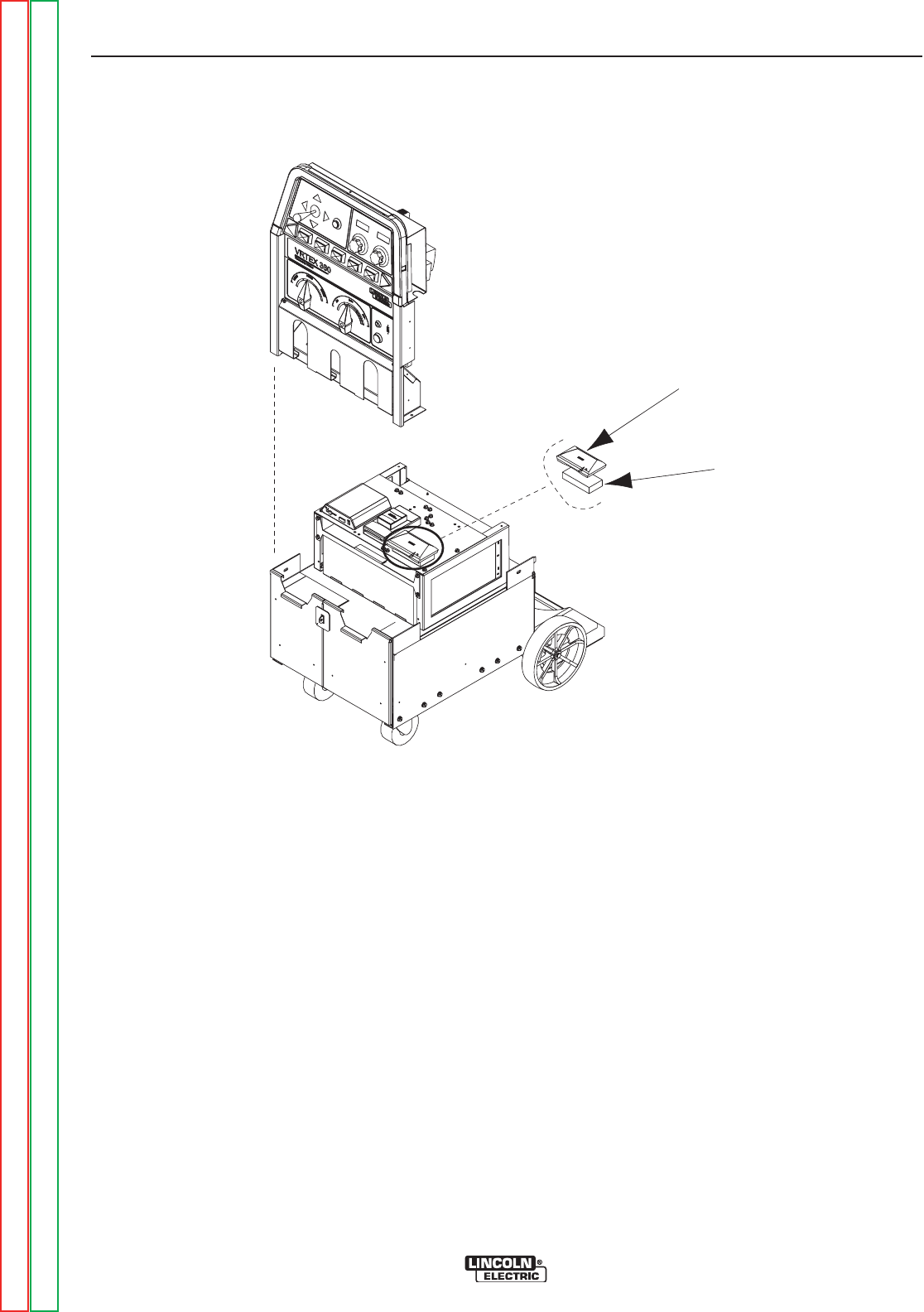
VGA SPLITTER
FMD CONTROLLER
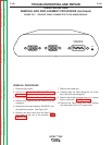
FIGURE F.45 – VGA SPLITTER LOCATION
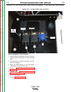
VGA SPLITTER REMOVAL AND REPLACEMENT PROCEDURE (continued)
REMOVAL PROCEDURE
1. Remove input power.
2. Perform the Monitor and Pedestal Removal
Procedure.
3. Perform the Case Cover Removal Procedure.
4. Locate the VGA Splitter. See Figure F.45.
5. To gain access to the VGA Splitter, carefully lift
and move the FMD controller aside.
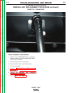
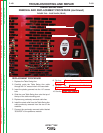
6. Label and remove the four cables connected to
the VGA Splitter. See Figure F.46.
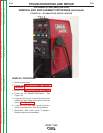
7. Remove the VGA Splitter Module from the hor-
izontal mounting shelf.
NOTE: The VGA Splitter is secured to the horizon-
tal mounting shelf with Hook & Loop mount-
ing pads.
TROUBLESHOOTING AND REPAIR
F-98 F-98
VRTEX
TM
360
Return to Section TOC Return to Section TOC Return to Section TOC Return to Section TOC
Return to Master TOC Return to Master TOC Return to Master TOC Return to Master TOC