


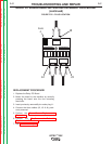

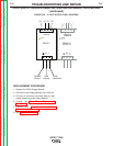

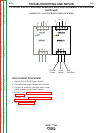

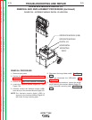
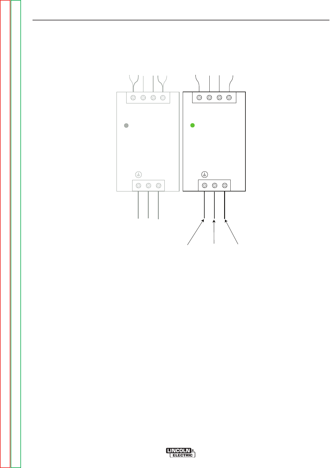
+ + - - + + - -
5VDC/5A5VDC/5A
DPP25-5DPP25-5
N LN L
DC ONDC ON
DPP50-15DPP50-15
+ + - - + + - -
15VDC/3.4A15VDC/3.4A
N LN L
D
C ONDC ON
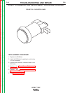
Ground
(Green)
102B
(White)
103C
(Pink/Red)
71
71 72 72
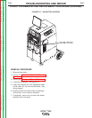
FIGURE F.26 – 12/15 VOLT SUPPLY LEAD LOCATIONS
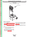
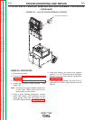
12/15VDC SUPPLY MODULE REMOVAL AND REPLACEMENT PROCEDURE
(continued)
REPLACEMENT PROCEDURE
1. Replace the 12/15VDC Supply Module.
2. Secure the new Supply Module to the DIN rail.
3. Connect all previously removed leads to their
proper locations on the Supply Module.
4. Perform the Case Cover Replacement
Procedure.
5. Perform the Monitor and Pedestal
Replacement Procedure.
6. See Retest After Repair.
TROUBLESHOOTING AND REPAIR
F-65 F-65
VRTEX
TM
360
Return to Section TOC Return to Section TOC Return to Section TOC Return to Section TOC
Return to Master TOC Return to Master TOC Return to Master TOC Return to Master TOC