


OPERATION
B-11 B-11
VRTEX
TM
360
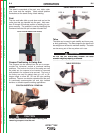
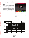
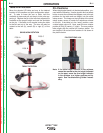
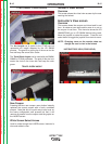
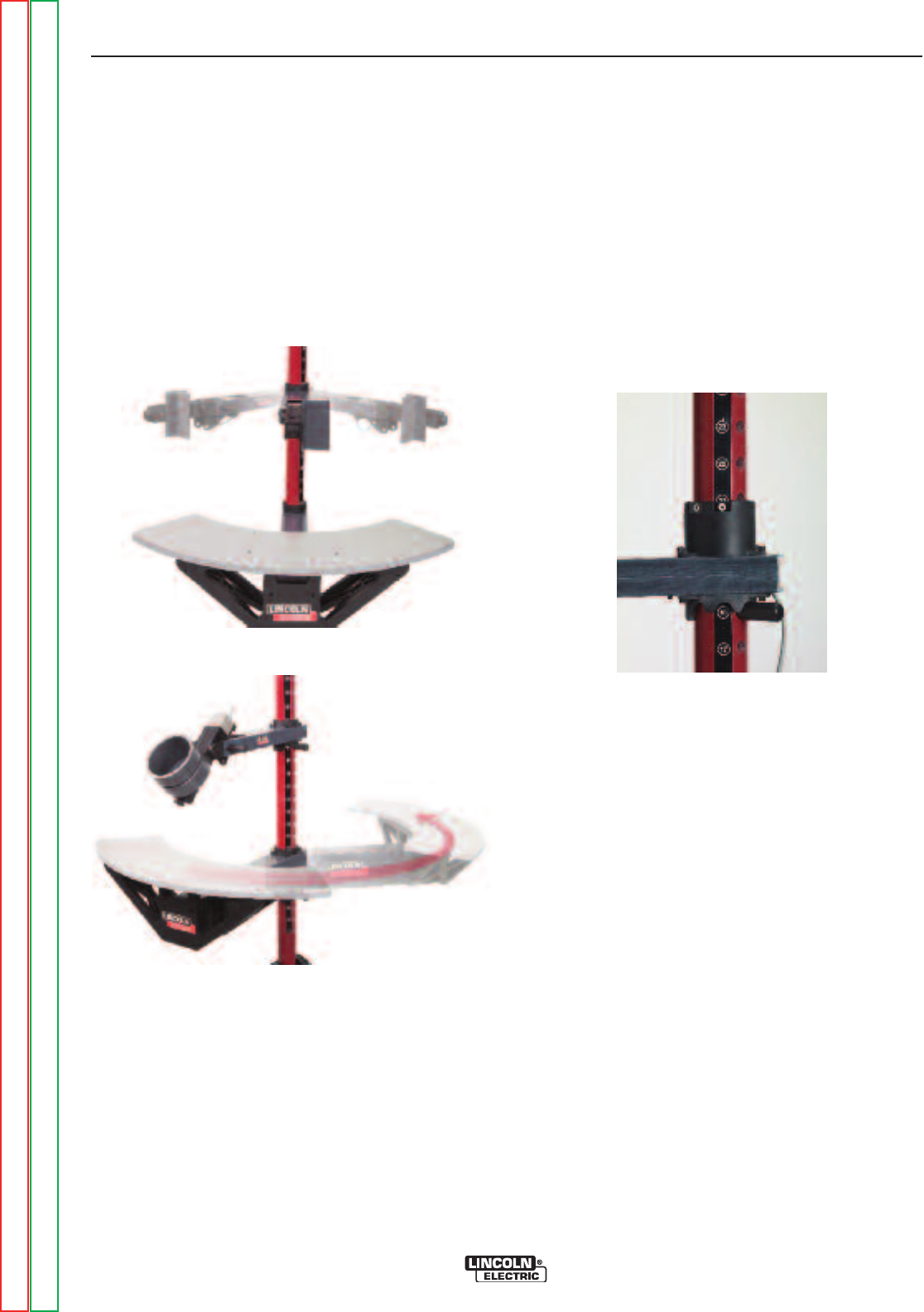
Table/Arm Rotation
Move the physical VR table and arm to the desired
location for the position and joint configuration select-
ed. To raise or lower the arm or table, hold the
arm/table in place and pull out the pin in the pole sup-
porting it. Replace the pin in the hole that supports the
arm/table at the proper height and rest the arm/table
on the pin. If the table is not needed, swing the table
to the left and out of the way. The arm can also be
rotated to the left (A), center (B) or right (C) of the
table.
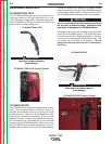
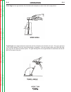
TABLE ROTATION
SWING ARM ROTATION
POS. A
POS. B
POS. C
Pin Positions
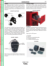
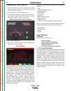
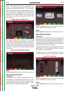
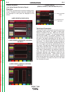
When the physical stand is in the desired position, pro-
ceed with the following: Use the joystick and red select
button to enter the numbers that appear next to the pin
positions for the table and arm height, into the stand
setup screen. The image on the right side of the stand
setup screen moves to match the selections entered
on the left. If the table is in the “away” position, enter
a table height value of 0. Next, enter the arm rotation
position A (left), B (center), C (right). The arm position
letter aligns with the vertical pin number sticker. An
arm height of 18 and and arm rotation of A is shown in
the picture below.
PIN POSITIONS 18 A
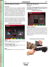
Note: If the table height indicator in the software
cannot be moved to the pin height indicated
on the post, move the arm height indicator
in the software to a higher position and try
again. See Troubleshooting Guide if neces-
sary.
Return to Section TOC Return to Section TOC Return to Section TOC Return to Section TOC
Return to Master TOC Return to Master TOC Return to Master TOC Return to Master TOC