


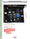


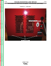
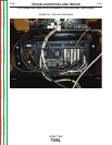
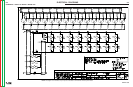
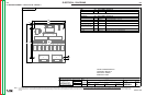

FIGURE F.50 – GROUND LEADS
CPU REMOVAL AND REPLACEMENT PROCEDURE (continued)
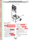
REPLACEMENT PROCEDURE
1. Attach Hook & Loop where necessary.
NOTE: Hook & Loop is supplied with new CPU.
2. Position new CPU into place between top and
bottom foam layers.
3. Install the four previously removed horizontal
mounting shelf screws.
NOTE: Make sure CPU ON/OFF switch is in the
“ON” position at all times.
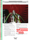
4. Connect the previously removed audio cable.
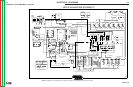
5. Connect the three previously removed VGA
cables. See wiring diagram.
6. Connect the five previously removed USB
cables. See wiring diagram.
7. Move the case back into the proper location and
secure using the three screws previously
removed.
8. Connect the previously removed external audio
jack into the CPU.
9. Install the strain relief securing the welding
stand cable.
10. Install and secure the three ground leads pre-
viously removed from inside of the case back.
11. Perform Case Cover Replacement
Procedure.
12. Perform the Monitor and Pedestal
Replacement Procedure.
13. Turn on input power
14. See the Retest After Repair.
NOTE: Make sure CPU ON/OFF switch is in the
“ON” position at all times.
TROUBLESHOOTING AND REPAIR
F-107 F-107
VRTEX
TM
360
Return to Section TOC Return to Section TOC Return to Section TOC Return to Section TOC
Return to Master TOC Return to Master TOC Return to Master TOC Return to Master TOC