


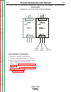
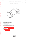

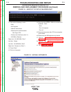
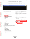


FIGURE F.30 – PLUG LOCATIONS
INTERFACE MODULE DIGITAL I/O
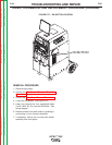
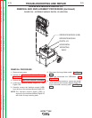
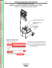
REMOVAL AND REPLACEMENT PROCEDURE (continued)
REPLACEMENT PROCEDURE
1. Install the new Interface Module Digital I/O and
secure using the previously removed screw.
2. Connect the previously removed USB cable.
3. Connect the large ribbon cable previously
removed.
NOTE: Make sure that the slide switch at the rear
of the Module is in the “HIGH” position.
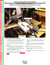
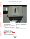
4. Connect USB mouse and USB keyboard to an
available/open USB port on CPU.
5. Turn on the input power to the machine.
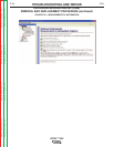
6. Wait for “Shortcut to Start-up Sim”. See Figure
F.31.
7. Click “x” to close screen and cancel loading. At
this point, a basic computer screen desktop will
appear.
8. Computer may show a “found new hardware”
screen. Click “next”. Then click on “connect to
internet”.
NOTE: Internet connection is not necessary.
9. Click on “Install the software automatically” and
then click “next”.
10. After the driver is installed successfully, click
“finished”.
TROUBLESHOOTING AND REPAIR
F-73 F-73
VRTEX
TM
360
SLIDE SWITCH
(Set to HIGH)
USB
RIBBON CABLE
SCREW
Return to Section TOC Return to Section TOC Return to Section TOC Return to Section TOC
Return to Master TOC Return to Master TOC Return to Master TOC Return to Master TOC