


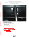

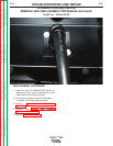


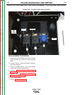
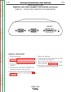

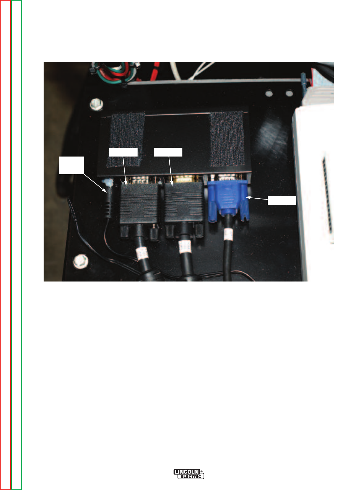
FIGURE F.46 – VGA SPLITTER LEAD LOCATION
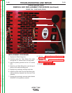
VGA SPLITTER REMOVAL AND REPLACEMENT PROCEDURE (continued)
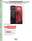
REPLACEMENT PROCEDURE
1. Install the new VGA Splitter onto the horizontal
mounting shelf using Hook & Loop mounting
pads.
2. Connect the four cables previously removed.
See wiring diagram.
3. Attach the FMD controller to the VGA Splitter
using Hook & Loop mounting pads.
4. Perform Case Cover Replacement
Procedure.
5. Perform the Monitor and Pedestal
Replacement Procedure.
6. Turn on input power
7. See the Retest After Repair.
TROUBLESHOOTING AND REPAIR
F-99 F-99
VRTEX
TM
360
VGA 2
VGA 6
VGA 1
DC
PLUG
Return to Section TOC Return to Section TOC Return to Section TOC Return to Section TOC
Return to Master TOC Return to Master TOC Return to Master TOC Return to Master TOC